Jeep Parts Wiki | Ford Parts Wiki
Home | Search | Browse
|
Corvair Chassis Shop Manual December 1964 |
|
Prev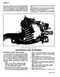
 Next
Next
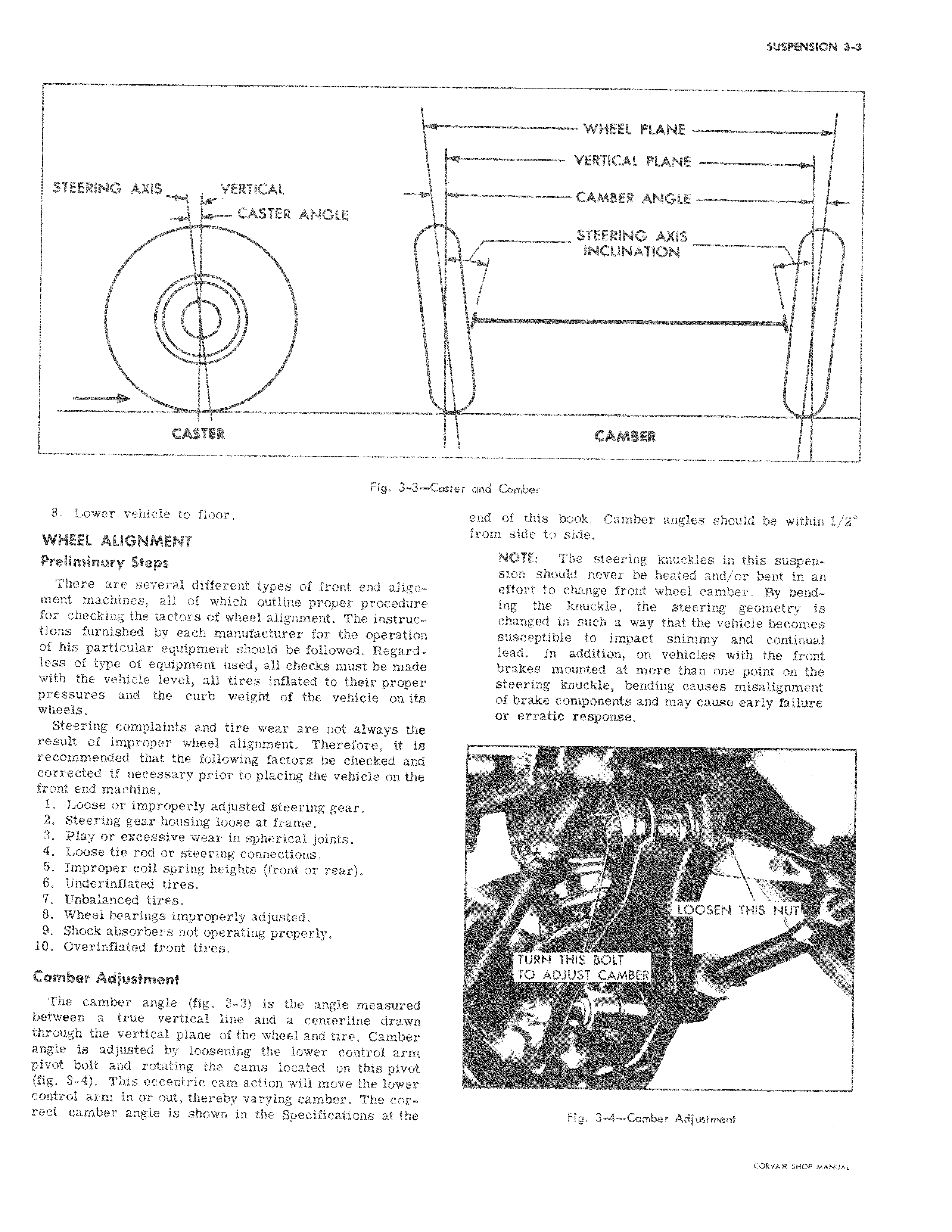
STEERING AXIS VERTICAL CASTER ANGLE CASTER Fig 3 3 Cost 8 Lower vehicle to floor WHEEL ALIGNMENT Preliminary Steps There are several different types of front end alignment machines all of which outline proper procedure for checking the factors of wheel alignment The instructions furnished by each manufacturer for the operation of his particular equipment should be followed Regardless of type of equipment used all checks must be made with the vehicle level all tires inflated to their proper pressures and the curb weight of the vehicle on its wheels Steering complaints and tire wear are not always the result of improper wheel alignment Therefore it is recommended that the following factors be checked and corrected if necessary prior to placing the vehicle on the front end machine 1 Loose or improperly adjusted steering gear 2 Steering gear housing loose at frame 3 Play or excessive wear in spherical joints 4 Loose tie rod or steering connections 5 Improper coil spring heights front or rear 6 Underinflated tires 7 Unbalanced tires 8 Wheel bearings improperly adjusted 9 Shock absorbers not operating properly 10 Overinflated front tires Camber Adjustment The camber angle fig 3 3 is the angle measured between a true vertical line and a centerline drawn through the vertical plane of the wheel and tire Camber angle is adjusted by loosening the lower control arm pivot bolt and rotating the cams located on this pivot fig 3 4 This eccentric cam action will move the lower control arm in or out thereby varying camber The correct camber angle is shown in the Specifications at the WHEEL PLANE VERTICAL PLANE CAMBER ANGLE o w w w v ar r STEERING AXIS INCLINATION CAMBER