Jeep Parts Wiki | Ford Parts Wiki
Home | Search | Browse
Prev

 Next
Next
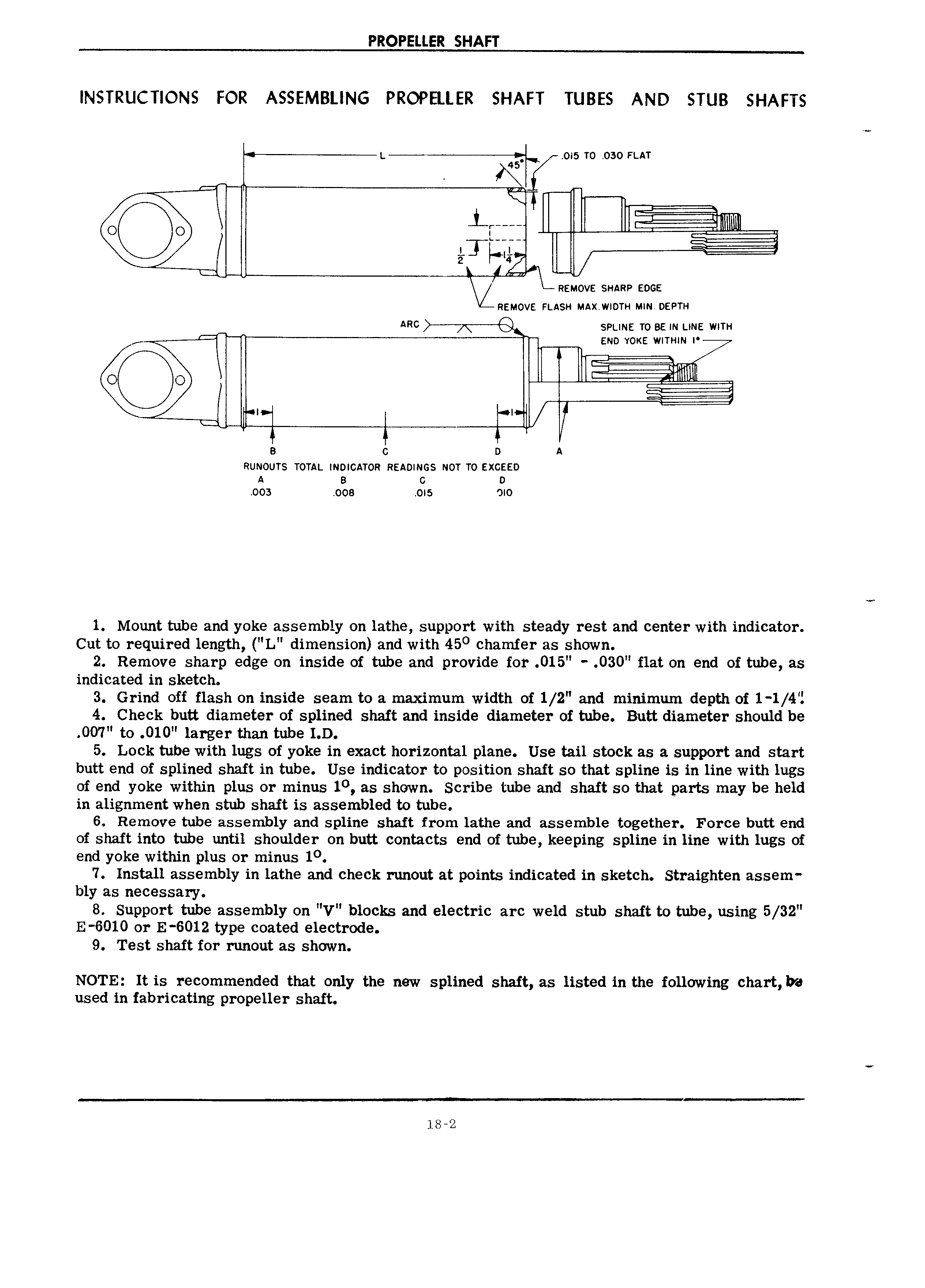
PROPELLER SHAFT INSTRUCTIONS FOR ASSEMBLING PROPELLER SHAFT TUBES AND STUB SHAFTS L 015 TO 030 FLAT N I 1 L RAAAA 1 2 REMOVE SHARP EDGE REMOVE FLASH MAX W DTH MIN DEPTH ARC S svunz TO sa IN una wma END YOKE WITHIN I O O I I X5 I I V a G A RUNOUTS TOTAL INDICATOR READINGS NOT TO EXCEED A B G D 003 008 OI5 JIO 1 Mount tube and yoke assembly on lathe support with steady rest and center with indicator Cut to required length L dimension and with 450 chamfer as shown 2 Remove sharp edge on inside of tube and provide for 015 030 flat on end of tube as indicated in sketch 3 Grind off flash on inside seam to a maximum width of 1 2 and minimum depth of 1 1 4 I 4 Check butt diameter of splined shaft and inside diameter of tube Butt diameter should be O07 to O10 larger than tube I D 5 Lock tube with lugs of yoke in exact horizontal plane Use tail stock as a support and start butt end of splined shaft in tube Use indicator to position shaft so that spline is in line with lugs of end yoke within plus or minus 10 as shown Scribe tube and shaft so that parts may be held in alignment when stub shaft is assembled to tube 6 Remove tube assembly and spline shaft from lathe and assemble together Force butt end of shaft into tube imtil shoulder on butt contacts end of tube keeping spline in line with lugs of end yoke within plus or minus 10 7 Install assembly in lathe and check runout at points indicated in sketch Straighten assem bly as necessary 8 Support tube assembly on V blocks and electric arc weld stub shaft to tube using 5 32 E 6010 or E 6012 type coated electrode 9 Test shaft for runout as shown NOTE It is recommended that only the new splined shaft as listed in the following chart be used in fabricating propeller shaft 18 2

 Next
Next