Jeep Parts Wiki | Ford Parts Wiki
Home | Search | Browse
|
Corvair Chassis Shop Manual Supplement December 1967 |
|
Prev

 Next
Next
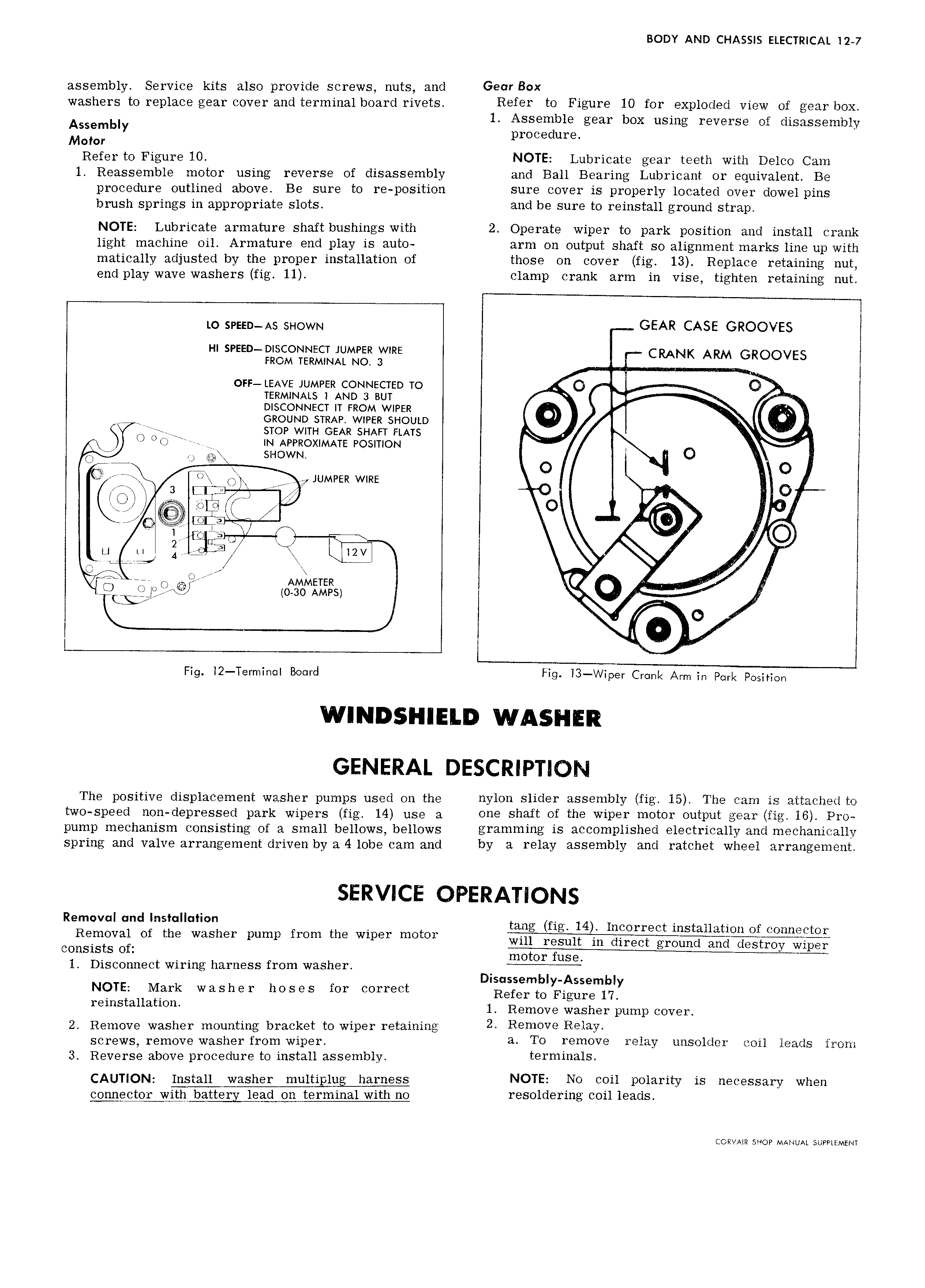
BODY AND CHASSIS ELECTRICAL l2 7 assembly Service kits also provide screws nuts and Gear Box washers to replace gear cover and terminal board rivets Refer to Figure 10 for exploded view of gear box Assembly 1 Assemble gear box using reverse of disassembly procedure Motor Refer to Figure 10 NOTE Lubricate gear teeth with Delco Cam 1 Reassemble motor using reverse of disassembly and Ball Bearing Lubricant or equivalent Be procedure outlined above Be sure to re position sure cover is properly located over dowel pins brush springs in appropriate slots and be sure to reinstall ground strap NOTE Lubricate armature shaft bushings with 2 Operate wiper to park position and install crank light machine oil Armature end play is auto arm on output shaft so alignment marks line up with matically adjusted by the proper installation of those on cover fig 13 Replace retaining nut end play wave washers fig 11 clamp crank arm in vise tighten retaining nut LO 5p55D A5 5 IOWN GEAR CASE GROOVES HI SPEED DIFCONNECT JUMPER WIRE CRA WAM TERMINAL N0 3 I I NK E 0EE LEAVE JUMPER CONNECTED TO Q TERMINALS I AND 2 Bur DISCONNECT IT FROM WIPER I I Ao oizoumo sTRAP WIPER SHOULD n g stop WITH GEAR sHAEr ELArs A I O Oo I IN APPROXIMATE POSITION O so U SHOWN V A A I I Q rr Q JUMPER WIRE J r 3 EI QQ I EVEK i s i I I i if I a 12 F A F 4 E K A UAA A Q E A R 7 i D JO E Ii O j I 2 MEt1Ii iiF S Q A it A I J Fig i2 Terminal Board Fig i3 Wiper Cromk Arm in Pork Position The positive displacement washer pumps used on the nylon slider assembly fig 15 The cam is attached to two speed non depressed park wipers fig 14 use a one shaft of the wiper motor output gear fig 16 Pro pump mechanism consisting of 3 small bellows bellows gramming is accomplished electrically and mechanically spring and valve arrangement driven by a 4 lobe cam and by a relay assembly and ratchet wheel arrangement R Q dQ L h f m th 1 K mm tw a r m V3 O 6 W S Gr puml TO 9 W pe will result in direct ground and destroy wiper consists of 1 Disconnect wiring harness from washer A Disassembly Assembly NOTE Mark washer hoses for correct Refer to Figure 17 r mStau t1 m 1 Remove washer pump cover 2 Remove washer mounting bracket to wiper retaining 2 R m0V9 Relay Screws remove Washer from wipe a To remove relay unsolder coil leads from 3 Reverse above procedure to install assembly t 1 miH8lS CAUTION Install washer multiplug harness NOTE N0 coil polarity is necessary when connego1 yv hA battery lead on terminal with no resoldering coil leads CORVAXR SHOP MANUAL SUPPLEMENT

 Next
Next