Jeep Parts Wiki | Ford Parts Wiki
Home | Search | Browse
|
Corvair Chassis Shop Manual Supplement December 1967 |
|
Prev

 Next
Next
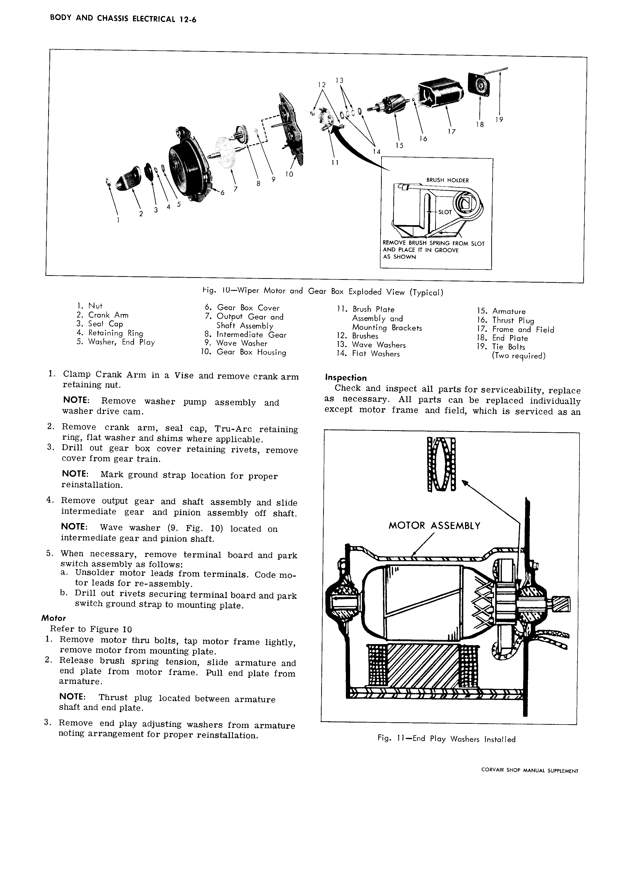
BODY AND CHASSIS ELECTRICAL I2 6 R QV Q 19 r V 5 at r 8 gl 1 E rl I l7 t 1 EEIIIII I5 lb I it Q if ld P git ll ll 3 lO be 8 9 BRUSH HOLDER 6 7 I E 3 A 5 1 l 2 Ramo s slot AND mcs IT IN cnoovr AS SHOWN tig U Wiper Motor and Gear Box Exploded View Typical l Nut 6 Gear Box Cover ll Brush Plate l5 Armature 2 Crank Arm 7 Output Gear and Assembly and l Thrust Plug 3 Seal Cap Shaft Assembly Mounting Brackets l7 Frome and Field 4 Retaining Ring 8 Intermediate Gear l2 Brushes l8 End Plate 5 Washer End Play 9 Wave Washer l3 Wave Washers l9 Tie Bolts lO Gear Box Housing l4 Flat Washers Two required 1 Clamp Crank Arm in a Vise and remove crank arm Inspection retaining nut Check and inspect all parts for serviceability replace as necessary All parts can be replaced individually Vllgllgr d u 3 Washer pump assembly and except motor frame and field which is serviced as an 2 Remove crank arm seal cap Tru Arc retaining ring flat washer and shims where applicable E i 3 Drill out gear box cover retaining rivets remove g cover from gear train if Q I l NOTE Mark ground strap location for proper reinstallation 4 Remove output gear and shaft assembly and slide intermediate gear and pinion assembly off shaft R AS EMBLY NOTE Wave washer 9 Fig 10 located on MOTO S intermediate gear and pinion shaft I 1 C 5 When necessary remove terminal board and park switch assembly as follows Ig 1 QIIII lll a Unsolder motor leads from terminals Code mo cg I L tor leads for re assembly 51 lA b Drill out rivets securing terminal board and park L T Q y switch ground strap to mounting plate Q 4 Q 4 1 Motor ji Refer to Figure 10 l 1 Remove motor thru bolts tap motor frame lightly 7 U 4 remove motor from mounting plate 2 Release brush spring tension slide armature and 2 3 end plate from motor frame Pull end plate from ggggg arrnature l K I 1 1 i 1II P IIIII I1 III FZ I 1 1 IIZ 17 NOTE Thrust plug located between armature shaft and end plate 3 Remove end play adjusting washers from armature noting arrangement for proper reinstallation Fig ll End Play Washers Installed CORVAIR SHOP MANUAL SUPPLEMENT

 Next
Next