Jeep Parts Wiki | Ford Parts Wiki
Home | Search | Browse
|
Corvair Chassis Shop Manual Supplement December 1967 |
|
Prev

 Next
Next
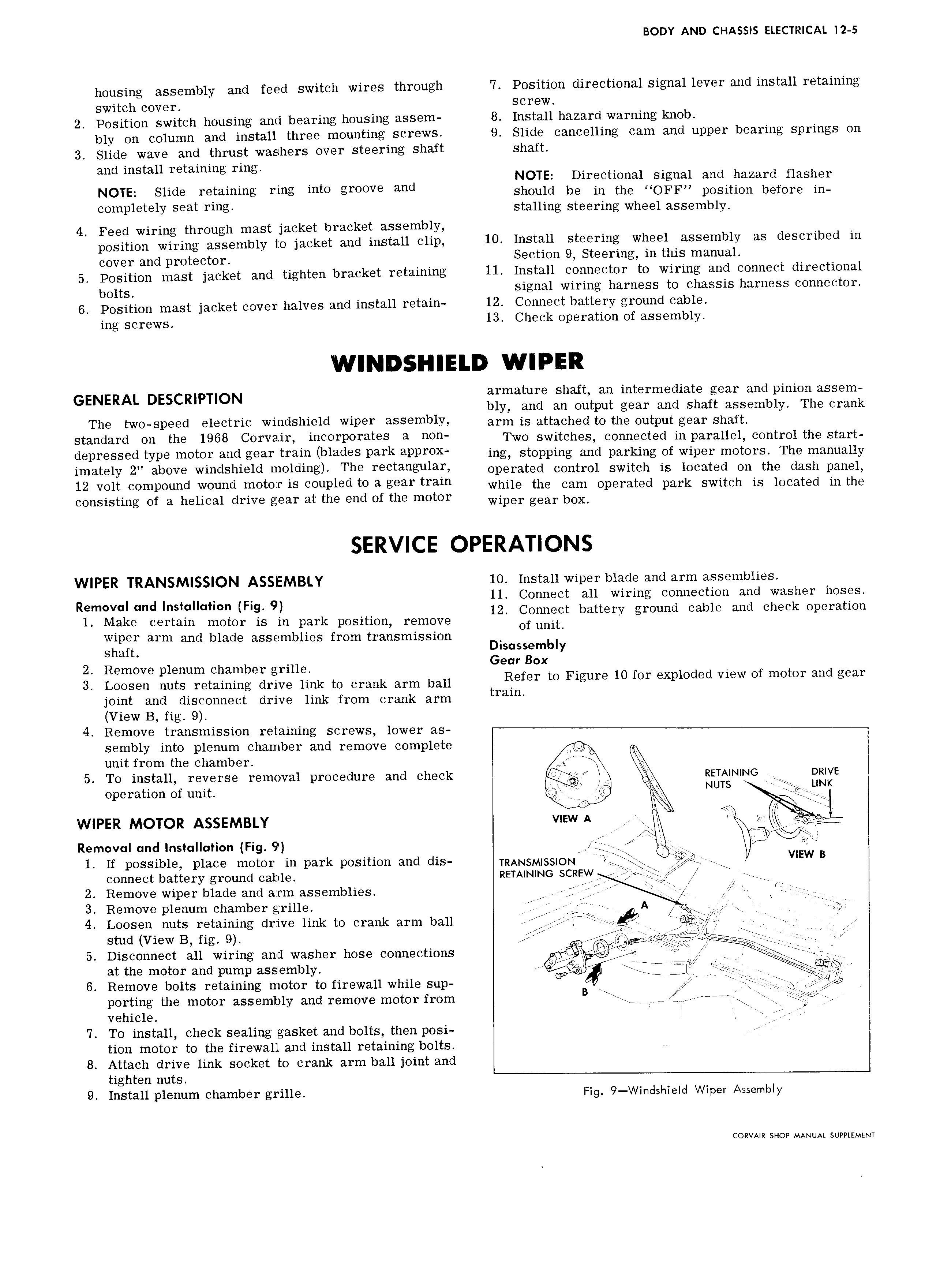
BODY AND CHASSIS ELECTRICAL I2 5 housing assembly and feed switch wires through 7 Position directional signal lever and install retaining switch cover screw 2 Position switch housing and bearing housing assem 8 Install hazard warning knob blv on column and install three mounting screws 9 Slide cancelling cam and upper bearing springs on 3 Slide wave and thrust washers over steering shaft shaft and install retaining ring NOTE Directional signal and hazard flasher NOTE Slide retaining ring into groove and Should be in the rrOFF position before m C0mP19t 1Y Seat Y mg stalling steering wheel assembly 4 Feed wiring through mast jacket bracket assembly position wiring assembly to jacket and install clip 10 Install steering wheel assembly as described in cover and protector Section 9 Steering in this manual 5 Position mast jacket and tighten bracket retaining 11 Install connector to wiring and connect directional bolts signal wiring harness to chassis harness connector 6 Position mast jacket cover halves and install retain 12 Connect battery ground cable ing screws 13 Check operation of assembly WINDSHIELD WIPER GENERAL DESCRIPTION armature shaft an intermediate gear and pinion assem bly and an output gear and shaft assembly The crank The two speed electric windshield wiper assembly arm is attached tu the Output guar Shaft Standard OH th 1968 COYVB il i 01 P0I t S 3 mm Two switches connected in parallel control the start depressed WPG m0t0F and g 31 train blades Park aPPI OX ing stopping and parking of wiper motors The manually imately 2 above Windshield mO1dmS The Yectangumfi operated control switch is located on the dash panel 12 volt compound wound motor is coupled to a gear train While the Cum Operated park switch is located in the consisting of a helical drive gear at the end of the motor Wiper guar bOX SERVICE OPERATIONS WIPER TRANSMISSION ASSEMBLY 10 Install wiper blade and arm assemblies 11 Connect all wiring connection and washer hoses Removal and Installation Fig 9 12 C t b tt d bl d h k t onnec a ery groun ca e an c ec opera ion 1 Make certain motor is in park position remove Of unit wiper arm and blade assemblies from transmission Shaft Disassembly 2 Remove plenum chamber grille Gear B X A 3 Loosen nuts retaining drive iirir to crank arm eeii Refer t0 Figure 10 M X 1 d V1 W Of mm md gw joint and disconnect drive link from crank arm tram View B fig 9 4 Remove transmission retaining screws lower as T sembly into plenum chamber and remove complete unit from the chamber A 5 To install reverse removal procedure and check i RETAINING omve operation of unit NUTS I A WIPER MOTOR ASSEMBLY v EwA ie Removal and Installation Fig 9 i up 1 If possible place motor in park position and dis TRANSMISSION iQ Q i WEW B connect battery ground cable RETAINING SCREW l T V 2 Remove wiper blade and arm assemblies j 1 V 3 Remove plenum chamber grille ix Ku 4 Loosen nuts retaining drive link to crank arm ball i ei 4 i z i L stud View B fig 9 I 5 Disconnect all wiring and washer hose connections w u 2 at the motor and pump assembly ia uu 6 Remove bolts retaining motor to firewall while sup t T7 A f jQg POYUHE UWB motor 3 SS mbly and remove motor from B u ur eee e gu i X vehicle I X 7 To install check sealing gasket and bolts then posi 4 tion motor to the firewall and install retaining bolts 8 Attach drive link socket to crank arm ball joint and tighten nuts 9 Install plenum chamber grille Fig 9 WindshieId Wiper Assembly CORVAIR SHOP MANUAL SUPPLEMENT

 Next
Next