Jeep Parts Wiki | Ford Parts Wiki
Home | Search | Browse
|
Corvair Chassis Shop Manual Supplement December 1967 |
|
Prev

 Next
Next
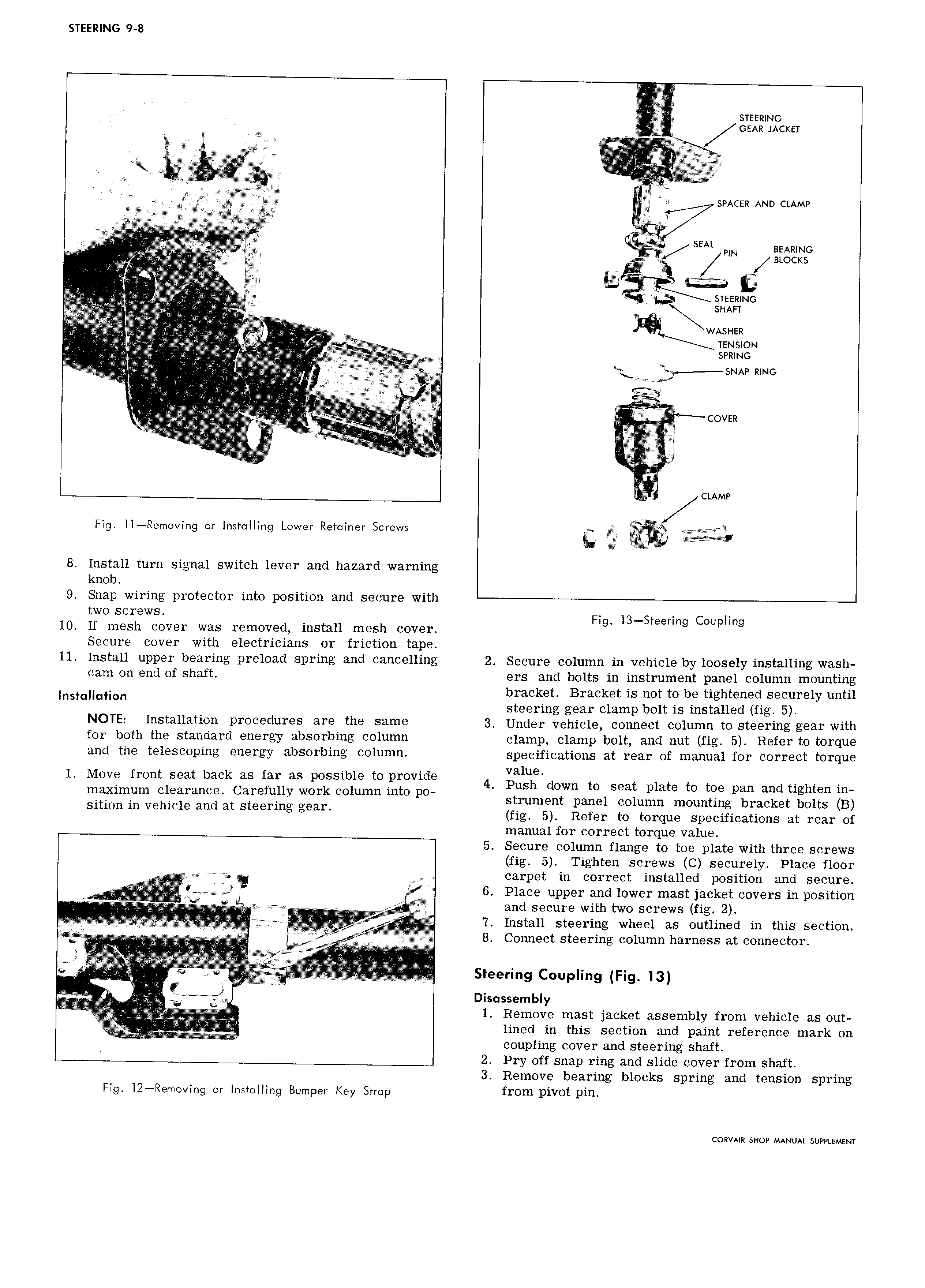
STEERING 9 8 F srsemwo V t KK GEAR JACKET L I EEA 2 F rr z il l J S A I EEEEEE E V VV SPACER AND CLAMP AA A A EE F A A A U r SEAL BEARING I A PIN I A L A V A is smzmwc i3 SHAFT AA V V I EE V A I WASHER AA A Tension v A Ar AJ Lf I A AA A FL VV j V QV S V V E V QL A WG AZKL 3 AA Egzlzzhihh ii A EA A VV 2V e VA P AAA AA i jjjj A corn VAAA AA I i i zi i CLAMP Fig ll Removing or Installing Lower Retainer Screws 8 Install turn signal switch lever and hazard warning knob 9 Snap wiring protector into position and secure with FWO Scr WS Fig l3 Steering Coupling 10 If mesh cover was removed install mesh cover Secure cover with electricians or friction tape 11 Install upper bearing preload spring and cancelling 2 Secure column in vehicle by loosely installing wash cam on end of shaft ers and bolts in instrument panel column mounting Insmuqnon bracket Bracket is not to be tightened securely until steering gear clamp bolt is installed fig 5 NOTE Installation procedures are the same 3 Under vcmcic connect column to steering gear with for both the standard energy absorbing column clamp clamp bolt and nut fig 5 Refer to torque and the telescoping energy absorbing column specifications at rear of manual for correct torque t d value l MOV from Seat back as far as possible Opmvl 9 4 Push down to seat plate to toe pan and tighten in maximum clearance Carefully work column 1HtO po t t hon in vehicle and at Steering gear s rumen panel column mounting bracket bolts B S1 fig 5 Refer to torque specifications at rear of manual for correct torque value 5 Secure column flange to toe plate with three screws fig 5 Tighten screws C securely Place floor Iljf V AA AAAAAA G Q V 1 carpet in correct installed position and secure A V K J 6 Place upper and lower mast jacket covers in position V I if A AAAA AAIl j V N and secure with two screws fig 2 V V IAIIIA W Vw I St2 11 St flflg wheel 3 S outlined in section ii i A A A i o Y VV V VVV V VVVVVV 8 Connect steering column harness at connector V g A V 9 B V V V VV VV V VV V VVV V Vy VVVV V Steering Coupling Fig T3 Disassembly VVV A V V VVVVVVVVVVVV 1 Remove mast jacket assembly from vehicle as out V V E VVVV lined in this section and paint reference mark on i V lili coupling cover and steering shaft 2 Pry off snap ring and slide cover from shaft 3 Remove bearing blocks spring and tension spring Fig l2 Removing or Installing Bumper Key Strap fI Om pivot pin CORVAIR SHOP MANUAL SUPPLEMENT

 Next
Next