Jeep Parts Wiki | Ford Parts Wiki
Home | Search | Browse | Marketplace | Messages | FAQ | Guest
|
Corvair Chassis Shop Manual Supplement December 1967 |
|
Prev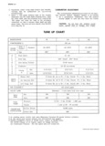
 Next
Next
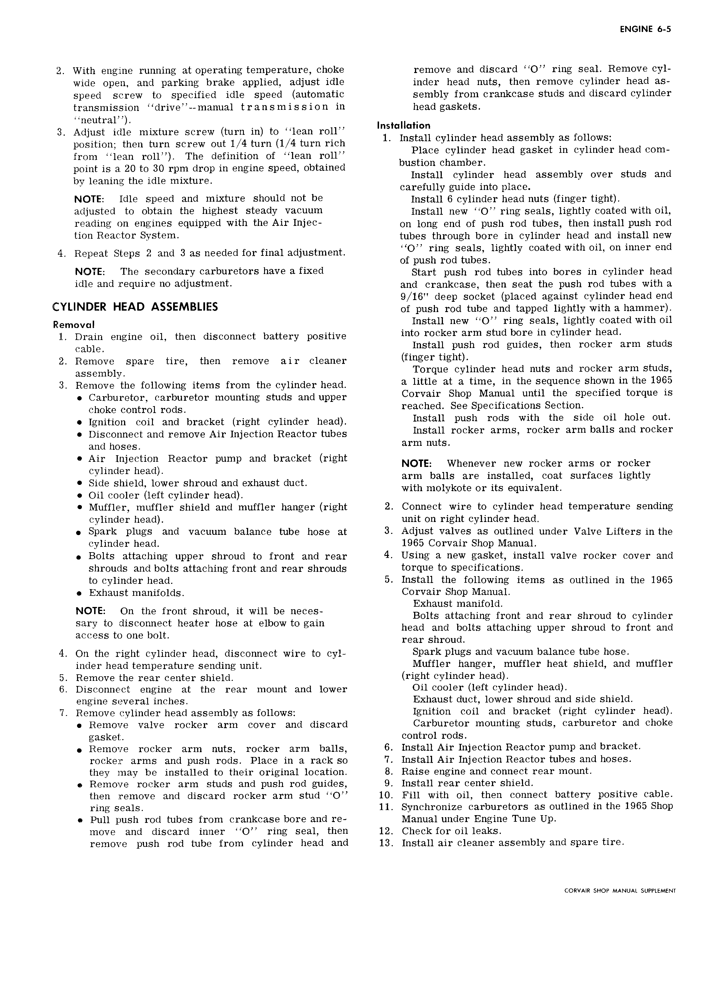
ENGINE 6 5 2 With engine running at operating temperature choke remove and discard O ring seal Remove cyl wide open and parking brake applied adjust idle inder head nuts then remove cylinder head as speed screw to specified idle speed automatic sembly from crankcase studs and discard cylinder transmission drive manual transmission in head gaskets neutral I t H t 3 Adjust idle mixture screw turn in to lean roll ns G G mn position then ooo ooooo ooo 1 4 ooo u 4 turn ooo 1 retail Cylinder head aSSemb1raef ews from lean roll roo definition of lean roll Place Gamer head gasket In erhnaet headtea point is a 20 to 30 rpm drop in engine speed obtained bustmn Chamber bv leaning the idle mjxtulg Install cylinder head assembly over studs and carefully guide into place NOTE Idle speed and mixture should net he fnstun 6 cylinder head nuts finger tight adjusted te ehtain the highest steady vaeuuni Install new toe ring seals lightly coated with bil reading en engines equipped with the Air 1nle OH long end er push resi tubes then install push rod tien Reaeter System tubes through bbre in cylinder head and install new 4 Repeat Steps ze and 3 oo neededfor final adjustment uns seals lightly eeated mth eu en mer and of push rod tubes NOTE The CO d3I Y C3 I buI tO S have 3 fiX 3d Start push rod tubes into bores in cylinder head idle and require ne adlusthuent and erenkeese then seat the push red tubes with e 9 16 deep socket placed against cylinder head end CYLINDER HEAD ASSEMBLIES of push rod tube and tapped lightly with a hammer Removal Install new O ring seals lightly coated with oil 1 Drain engine oil then disconnect battery positive into reeker arm stud herein Cylinder nsad Cable Install push rod guides then rocker arm studs 2 Remove spare tire then remove air cleaner finger rignr assembly Torque cylinder head nuts and rocker arm studs 3 Remove the following items from the cylinder head a little at a rims in tnn sequence snnwn inthe 1965 Carburetor carburetor mounting studs and upper Corvair Snnp Manual until the Speeified ternue is Choke Control I OdS reached See Specifications Section Ignition coil and bracket right cylinder head install push reds Wnn rnn side On nnle Our Disconnect and remove Air Injection Reactor tubes Install reeker ar ns reeker arm bans and rocker and hoses arm nnts Air Injection Reactor pump and bracket right NOTE Whenever new rocker arms Or rocker Cy1md rh z d arm balls are installed coat surfaces lightly Side shield lower shroud and exhaust duct with mol kote Or its 9 ui alent Oil cooler left cylinder head Y q Muffler muffler shield and muffler hanger right 2 Connect wire to cylinder head temperature sending cylinder head unit on right cylinder head Spark plugs and vacuum balance tube hose at 3 Adjust valves as outlined under Valve Lifters in the cylinder head 1965 Corvair Shop Manual Bolts attaching upper shroud to front and rear 4 USi g 9 W guskdt install valve 1 00k I COVGY and shrouds and bolts attaching front and rear shrouds t01 qu te specifications to cylinder head 5 Install the following items as outlined in the 1965 Exhaust manifolds Corvair Shop Manual Exhaust manifold gggzsio C E O 2aig O ggBltazvtgbgi in Bolts attaching front and rear shroud to cylinder mpegs to one bolt head and bolts attaching upper shroud to front and rear shroud 4 On the right cylinder head disconnect wire to cyl Spark P1ugS aud Vacuum b3 13 tube hose lnder head temperature sending unit Muffler hanger muffler heat shield and muffler 5 Remove the rear center shield right cylinder head 6 Disconnect engine at the rear mount and lower OU eeeler left CYUHGBF h 3d engine several inches Exhaust duct lower shroud and side shield 7 Remove cylinder head assembly as tunbws Ignition evil and bracket right eylinder headl Remove valve rocker arm cover and discard Carburetor mounting studs carburetor and choke gasket control rods Remove rocker arm nut5 rocker arm balls 6 Install Air Injection Reactor pump and bracket rocker arms and push rods Place in a rack so 7 Install Air Injection Reactor tubes and hoses they may be installed to their original location 8 Raise engine and connect rear mount Remove rocker arm studs and push rod guides 9 Install rear center shield then remove and discard rocker arm stud O 10 Fill with oil then connect battery positive cable ring seals 11 Synchronize carburetors as outlined in the 1965 Shop Pull push rod tubes from crankcase bore and re Manual under Engine Tune Up move and discard inner O ring seal then 12 Check for oil leaks remove push rod tube from cylinder head and 13 Install air cleaner assembly and spare tire CORVAIR SHOP MANUAL SUPPLEMENT