Jeep Parts Wiki | Ford Parts Wiki
Home | Search | Browse
|
Corvair Chassis Shop Manual Supplement December 1967 |
|
Prev

 Next
Next
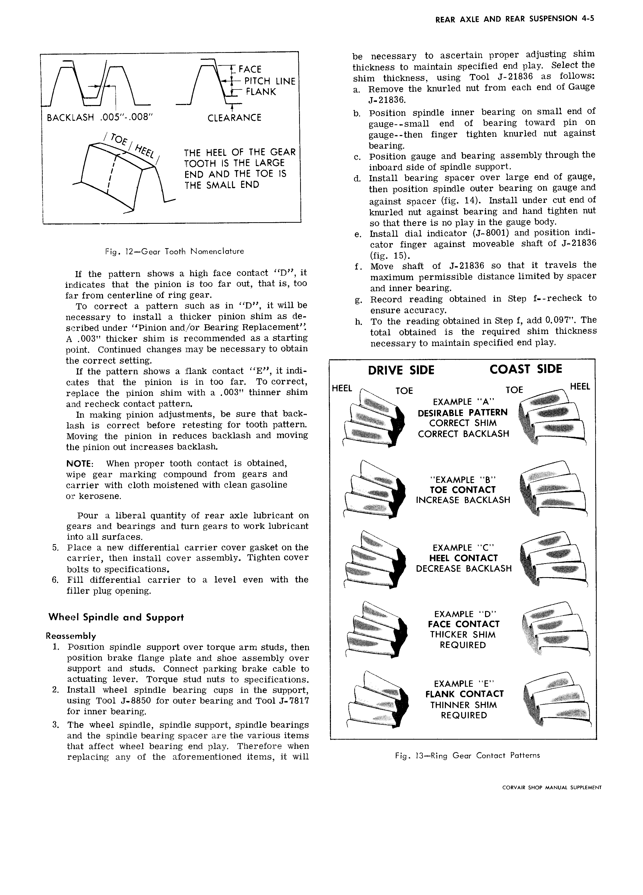
REAR AXLE AND REAR SUSPENSION 4 5 be necessary to ascertain proper adjusting shim FACE thickness to maintain specified end play Select the pL CH LINE shim thickness using Tool J 21836 as follows FLANK a Remove the knurled nut from each end of Gauge J 21836 BACKLASH OO5 OO8 CLEARANCE b Position spindle inner bearing on small end of gauge small end of bearing toward pin on TOE gauge then finger tighten knurled nut against Fs EL ot THE GEAR bearing 1 HE HE c Position gauge and bearing assembly through the EIEOOTH Ig ETg GIg inboard side of spindle support FN ALL END d Install bearing spacer over large end of gauge H then position spindle outer bearing on gauge and T against spacer fig 14 Install under cut end of i knurled nut against bearing and hand tighten nut l so that there is no play in the gauge body e Install dial indicator J 8001 and position indi bl h ft f J 21836 Fig l2 Geer Tooth Nomenclature Ffzi orlggnger against movea G S 3 O f M h ft f J 21836 tht t t l th H the pattern Shows a high face Contact D It mggigmnima ercinissible disisnce Eiimlitedrggesgacei indicates that the pinion is too far out that is too p fe from t r of mg gm EZIZ E Z S T ggtt tn d in St f echeti to To correct a pattern such as in D it will be g Ensure accuraci p necessary to install a thicker pinion shim as de h scribed under Pinion and or Bearing Replacement h zgagheogtiiggglg gtaiggd qit 1 g H CEnr S A O03 thicker shim is recommended as a starting t R tam S Ecmed End la point Continued changes may be necessary to obtain necessary O m m p p y the correct setting ii the pattern shows ii nank contact HE it indi DRIVE SIDE COAST SIDE cates that the pinion is in too far To correct HEEL replace the pinion snnn with a 003 tninner shim HEEL TOE TOE l E and recheck contact pattern EXAMPLE A E V 5 it J A In making pinion adjustments be sure that back DESIRABLE PATTERN E EE lash is correct before retesting for tooth pattern i T T i CORRECT SHIM H Moving the pinion in reduces backlash and moving CORRECT BACKLASH the pinion out increases backlash NIOTE When proper tooth contact is obtained wipe gear marking compound from gears and carrier with cloth moistened with clean gasoline T Tg Aggr fTAgT t A YAV OT k S INCREASE BACKLASH il E i T Pour a liberal quantity of rear axle lubricant on V A gears and bearings and turn gears to work lubricant into all surfaces 5 Place a new differential carrier cover gasket on the E EXAMPLE C carrier then install cover assembly Tighten cover e HEEL CQNTACT bolts to specifications DECREASE BACKLASH 6 Fill differential carrier to a level even with the A filler plug opening Wheel Spindle and support iti EXAMPLE o FACE CONTACT Reussembly THICKER SHIM 1 Position spindle support over torque arm studs then W E REQUIRED position brake flange plate and shoe assembly over support and studs Connect parking brake cable to actuating lever Torque stud nuts to specifications 2 Install wheel spindle bearing cups in the support ELi A I2AI E NTEE CT A using Tool J 8850 for outer bearing and Tool J 7817 A THINNER SHIM for inner bearing EE REQUIRED 3 I he wheel spindle spindle support spindle bearings if EEV A E and the spindle bearing spacer are the various items that affect wheel bearing end play Therefore when replacing any of the aforementioned items it will Fig 13 Ring Geor Ccnmct Puttems CORVAIR SHOP MANUAL SUPPLEMENT

 Next
Next