Jeep Parts Wiki | Ford Parts Wiki
Home | Search | Browse
|
Corvair Chassis Shop Manual Supplement December 1966 |
|
Prev
 Next
Next
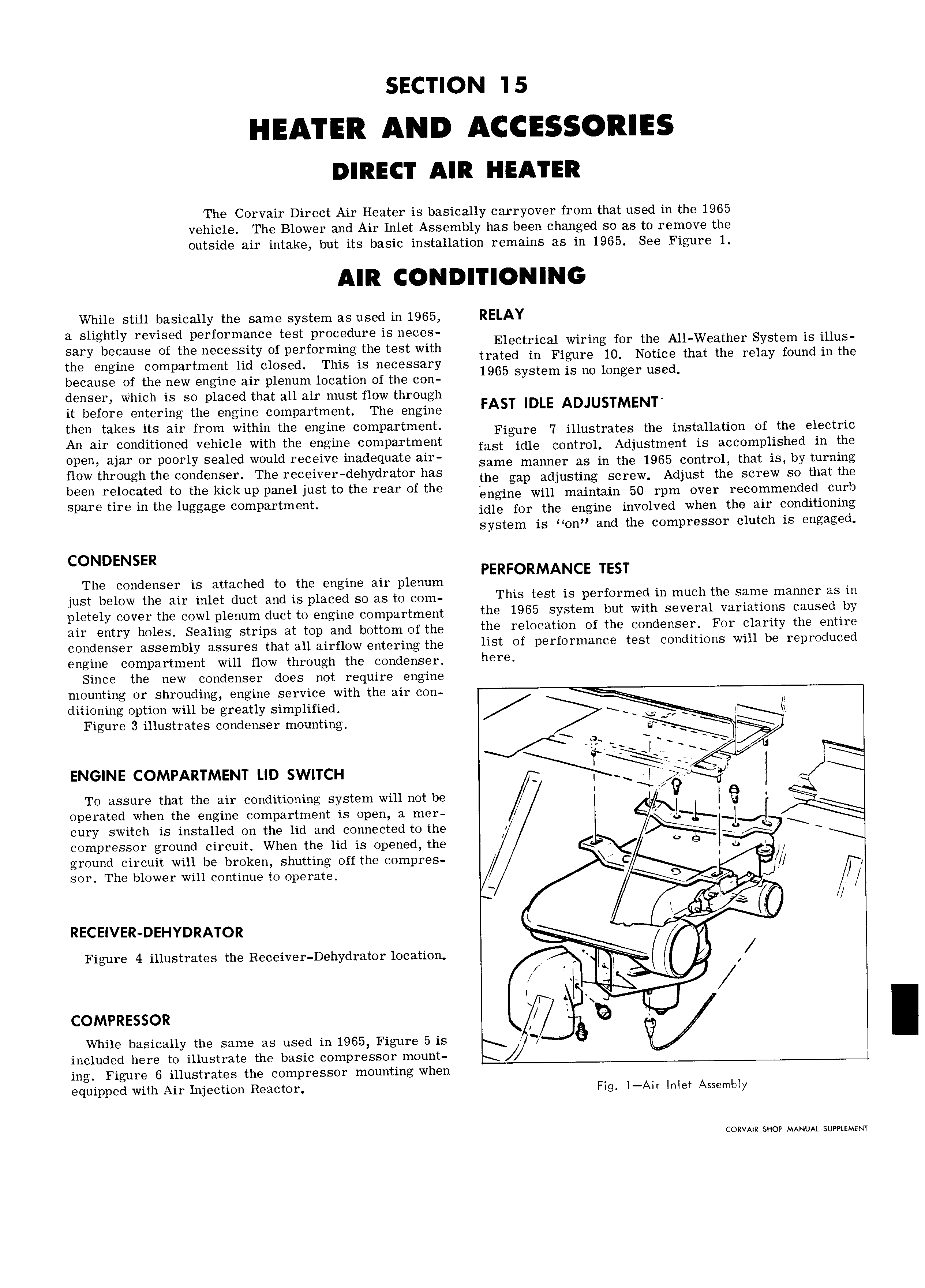
The Corvair Direct Air Heater is basically carryover from that used in the 1965 vehicle The Blower and Air Inlet Assembly has been changed so as to remove the outside air intake but its basic installation remains as in 1965 See Figure 1 While sun basically the Same system as used in 1965 RELAY 1 htl d 3 S lg Y TBVISQ performaince test p d IS H C S Electrical wiring for the All Weather System is illus sary because of the necessity of performing the test with trated in Figure 10 Notice that the relay found in the the engine compartment lid closed This is necessary 1965 S St m is no nm er used because of the new engine air plenum location of the con y e g denser which is so placed that all air must flow through it before entering the engine compartment The engine FAST IDLE ADJUSTMENT then takes its air from within the engine compartment Figure 7 illustrates the installation ot the electric An air condit ioned vehicle with the engine compartment inst idle enntl Ol Adjustment is accomplished in the Op n glu or poorly Sealed Would receive i d t ah same manner as in the 1965 control that is by turning flow through the condenser The receiver dehydrator has the gan adjusting set eW Adjust the screw so that the been relocated to the kick up panel just to the rear of the nngine will maintain 50 rum over recommended curb Spam tue m the luggage compartment idle for the engine involved when the air conditioning system is on and the compressor clutch is engaged CONDENSER PERFORMANCE TEST The condenser is attached to the engine air plenum A t just below the air inlet duct and is placed so as to com Thls test ls P rformefl m much the Slflmfi mamgr as m pletely cover the cowl plenum duct to engine compartment the 1965 SYSl m but Wlth Several v r1 S caused bY air entry hoteS gedllng Strips at tgp and bottom of the the relocation of the condensert For elarity the entire condenser assembly assures that all airflow entering the 1lSt Of P Y f0i m3 C test COUCUUOUS W111 bl Yepmduced engine compartment will flow through the condenser here Since the new condenser does not require engine mounting or shrouding engine service with the air con I ditioning option will be greatly simplified ss I Figure 3 illustrates condenser mounting ENGINE COMPARTMENT up swncu A I ygJ tIF I 9 To assure that the air conditioning system will not be I I I 9 operated when the engine compartment is open a mer I cury switch is installed on the lid and connected to the I 3 compressor ground circuit When the lid is opened the u ground circuit will be broken shutting off the compres ic I sor The blower will continue to operate I Jl l et I i L I 0 RECEIVER DEHYDRATOR n Figure 4 illustrates the Receiver Dehydrat0r 1OC3ti0H ix I COMPRESSOR l Q While basically the same as used in 1965 Figure 5 is 7 included here to illustrate the basic compressor mount ing Figure 6 illustrates the compressor mounting when equipped with Air Injection Reactor Fig l AIr Inlet Assembly CORVAIR SHOP MANUAL SUPPLEMENT