Jeep Parts Wiki | Ford Parts Wiki
Home | Search | Browse
|
Corvair Chassis Shop Manual Supplement December 1966 |
|
Prev

 Next
Next
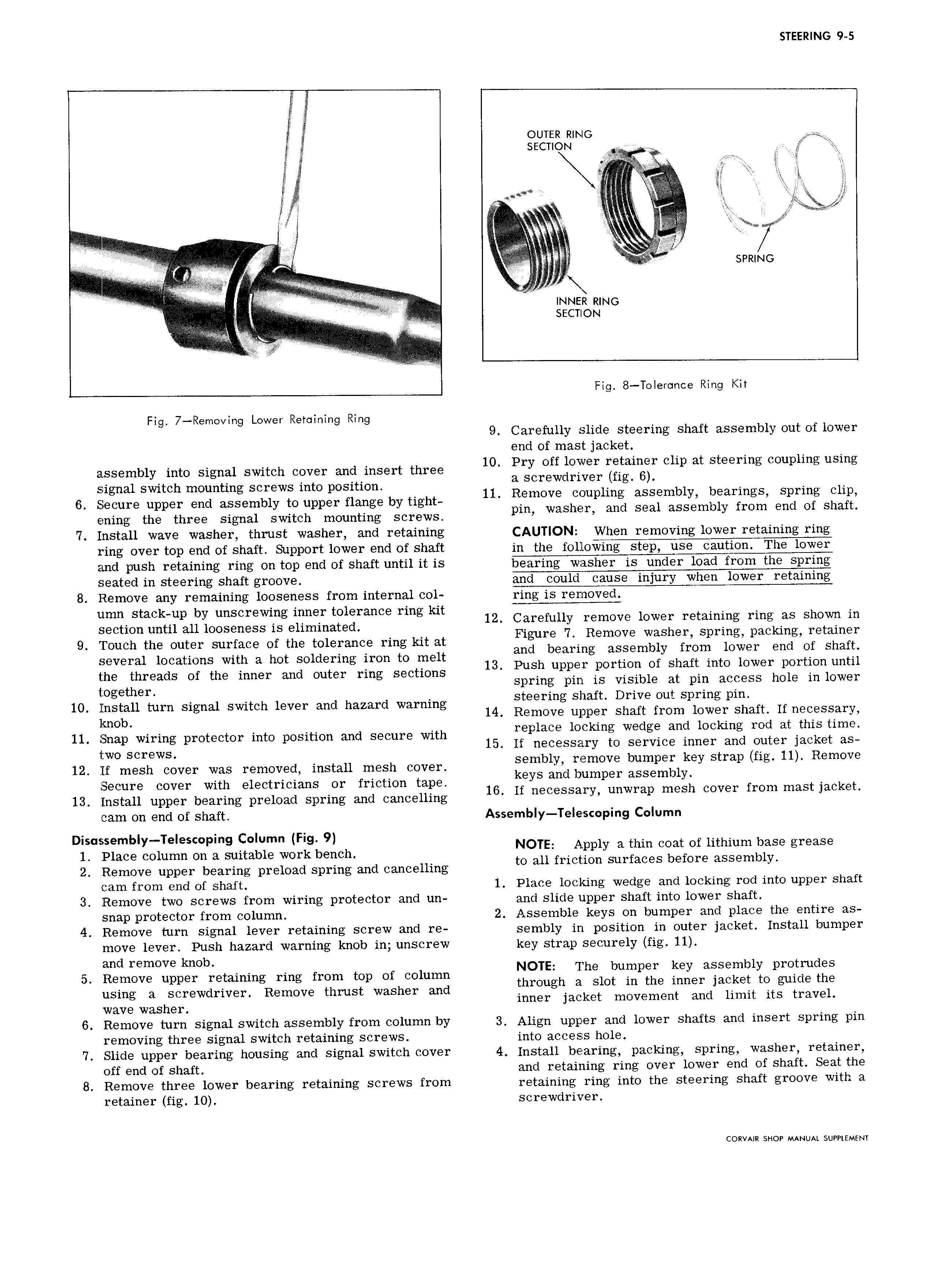
STEERING 9 5 outta RING secmx N gb N T Q C I K E i L E EE 7 L A E E EE I S rz SPRING rr L 7 V V V rr i t V F if EEEEEEEEE EEEE EEE 2 E EEE Y EEE EEEEEEEEEEE E E E I E INNER RING t IA III I RR R N N II IGEER n A IIIIIII IIR Fig 8 Tolerance Ring Kit Fig 7 Rernoving Lower Retaining Ring 9 Carefully slide steering shaft assembly out of lower end of mast jacket assembly into signal switch cover and insert three 1O pry Off goiwer I italzer Chp at steermg couplmg usmg signal switch mounting screws into position 11 SCr W mverl lg bl b 1 6 Secure upper end assembly to upper flange by tight mOV up mi ass y b ar ngS Salim E15 ening the three signal switch mounting screws pm was r an Sea assem y mm en O S 3 7 Install wave washer thrust washer and retaining CAUTION When removing lower retaining ring ring over top end of shaft Support lower end of shaft in the following step use caution The lower and push retaining ring on top end of shaft until it is bearing washer is under load from the spring seated in steering shaft groove and could cause injury when lower retaining 8 Remove any remaining looseness from internal col ring is removed umn stack up by unscrewing inner tolerance ring kit section until all looseness is eliminated l2 iarefullg Igimove Iowa renaming rmgkias Sho m 9 Touch the outer surface of the tolerance ring kit at lim Bmove VSS E Spmf1g pac r 1g QQ Agn several locations with a hot soldering iron to melt 13 n h Garmg aijsem fy hrgni tmiver en E S afi t he threads of the inner and outer ring sections Sgingupgir Orviglfbfjg it apilinaicggerhggr Enlglxelr t ogether L 10 Install turn signal switch lever and hazard warning Steering Shaft DUVG out Sprmg pm knob 14 Remove upper shaft from lower shaft If necessary 11 Snap wiring protector into position and secure with rigplace lockmg Wedg an lockmg md at th1S Uma two Screws 15 If necessary to service inner and outer jacket as 12 If mesh cover was removed install mesh cover iemblyhgamove bumpeglkey Strap fig my Remove Secure cover with electricians or friction tape 16 IFYS an umper assem yi f t k t 13 Install upper bearing preload spring and cancelling C SS3ry Lmwmp mes Cover mm mas Jac 6 cam on end of shaft Assembly Te e scoping Column Dis sasemb y TeIesc0ping Column Fig 9 1 Place column on a suitable work bench 40 Iifzf ifpply a thm Cc atfof lithium SFSB grease 2 Remove upper bearing preload spring and cancelling O 3 mc mn Sur aces 6 Ore assgm y cam from end of shaft 1 Place locking wedge and locking rod into upper shaft 3 Remove two screws from wiring protector and un and slide upper shaft into lower shaft snap protector from column 2 Assemble keys on bumper and place the entire as 4 Remove turn signal lever retaining screw and re sembly in position in outer jacket Install bumper move lever Push hazard warning knob in unscrew key strap securely fig 11 d k 5 gn remove mib NOTE The bumper key assembly protrudes emove upper retaining ring from top of column using a screwdriver Remove thrust washer and through 3 Slot m the Umar Jacket to guide the inner jacket movement and limit its travel wave washer 6 Remove turn signal switch assembly from column by 3 Align upper and lower shafts and insert spring pin removing three signal switch retaining screws into access hole 7 Slide upper bearing housing and signal switch cover 4 Install bearing packing spring washer retainer off end of shaft and retaining ring over lower end of shaft Seat the 8 Remove three lower bearing retaining screws from retaining ring into the steering shaft groove with a retainer fig 10 screwdriver CORVAIR SHOP MANUAL SUPPLEMENT

 Next
Next