Jeep Parts Wiki | Ford Parts Wiki
Home | Search | Browse
|
Corvair Chassis Shop Manual Supplement December 1966 |
|
Prev

 Next
Next
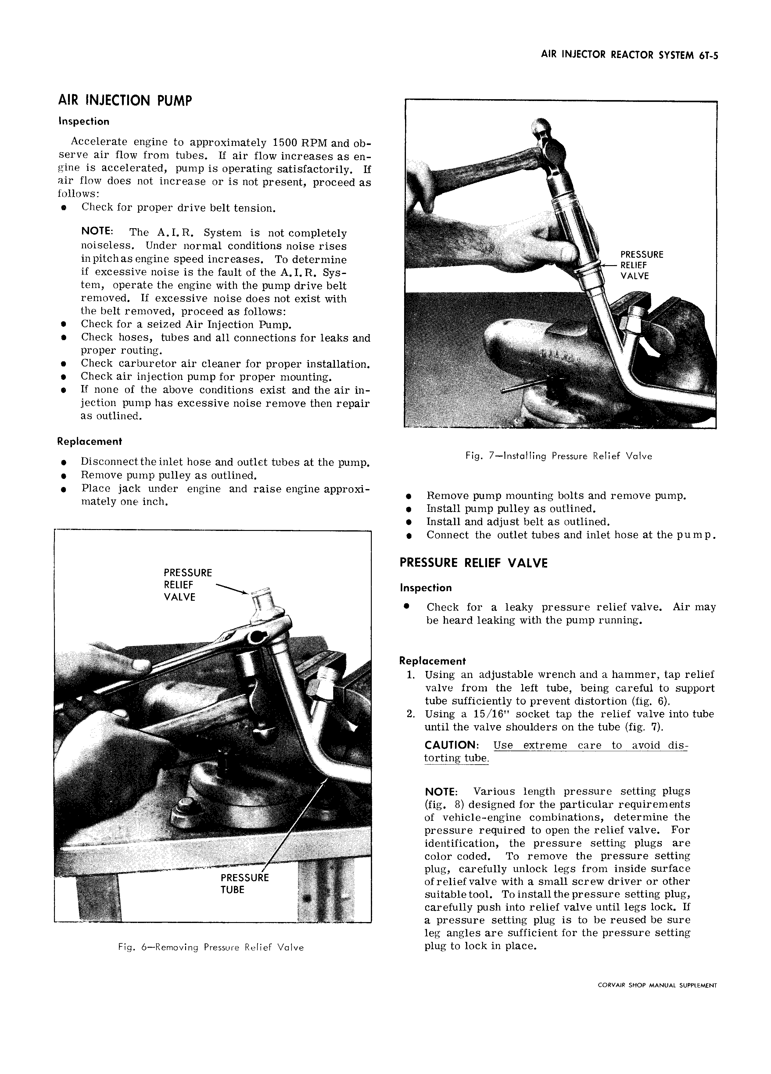
AIR INJECTOR REACTOR SYSTEM 6T 5 AIR INJECTION PUMP Inspection E Accelerate engine to approximately 1500 RPM and ob serve air flow from tubes If air flow increases as en gine is accelerated pump is operating satisfactorily If g I N air flow does not increase or is not present proceed as r AV A follows j Check for proper drive belt tension l NOTE The A I R System is not completely lghy l noiseless Under normal conditions noise rises I 1 l PRESSURE in pitch as engine speed increases To determine t RELIEF if excessive noise is the fault of the A I R Sys vA vE tem operate the engine with the pump drive belt It 1 by removed If excessive noise does not exist with I I i the belt removed proceed as follows I I N g V R i g Check for a seized Air Injection Pump W tt 3 I a t Check hoses tubes and all connections for leaks and TV PYOPGP F s I I Check carburetor air cleaner for proper installation M VI V Check air injection pump for proper mounting W f g i If none of the above conditions exist and the air in AV g ea Q jection pump has excessive noise remove then repair q g as outlined I W Replacement F 7 ItII P RI FVI Disconnect the inlet hose end eutiet tubes at the pump 9 S Q wwe 6 E V8 Remove pump pulley as outlined Place jackrunltller engine and raise engine approxi Remove pump mounting bolts and remove pump mate Y one mc Install pump pulley as outlined Install and adjust belt as outlined Connect the outlet tubes and inlet hose at the pump PRESSURE RELIEF VALVE PRESSURE gk Inspection Check for a leaky pressure relief valve Air may fz V be heard leaking with the pump running Qt Z I M K J r eti I L I i ILIL i R p m E E Q2 j 1 Using an adjustable wrench and a hammer tap relief W valve from the left tube being careful to support 4 r Vlggjgggj I tube sufficiently to prevent distortion fig 6 I 2 Using a 15 16 socket tap the relief valve into tube g i if gp until the valve shoulders on the tube fig 7 e s E l g g C USG Extreme care tO avoid djs X I iii r N i I i gee we I X VIII i i rt 4 NOTE Various length pressure setting plugs I fig 8 designed for the particular requirements of vehicle engine combinations determine the i f I I I pressure required tO Open relief va 1V FOI erceeree A ticll I 3 identification the pressure setting plugs are c I I It IIIIII II t r 1 d d T more the pressure setting ii iii Else celrrr tereu ji I C0 Or C0 P O re aw plug carefully unlock legs from inside surface r PRESSURE 3 of relief valve with a small screw driver or other T TUBE suitable tool To install the pressure setting plug r carefully push into relief valve until legs lock If Y i a pressure setting plug is to be reused be sure leg angles are sufficient for the pressure setting Fig 6 Rerno Ing Pressure ReIIeF Ive Plug to lock in place CORVAIR SHOP MANUAL SUPPLEMENT

 Next
Next