Jeep Parts Wiki | Ford Parts Wiki
Home | Search | Browse
|
Corvair Chassis Shop Manual Supplement December 1965 |
|
Prev
 Next
Next
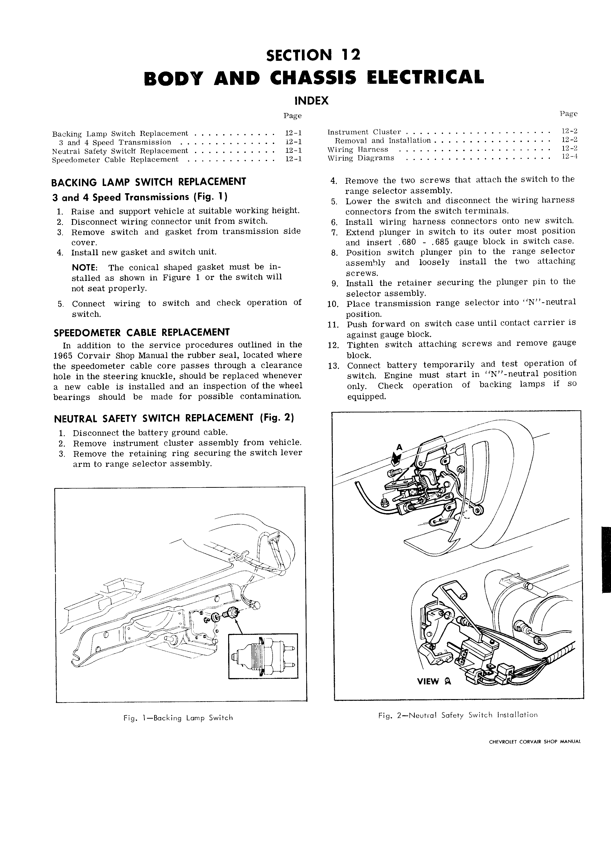
INDEX Page Page Backing Lamp Switch Replacement 12 1 Instrument Cluster 12 2 3 and 4 Speed Transmission 12 1 Removal and Installation 12 2 Neutral Safety Switch Replacement 12 1 Wiring Harness 12 2 Speedometer Cable Replacement 12 1 Wiring Diagrams 12 4 BACKING LAMP SWITCH REPLACEMENT 4 Remove the two screws that attach the switch to the range selector assembly 3 and 4 Speed Tmnsmlsswns FIg ll 5 Lower the switch and disconnect the wiring harness 1 Raise and support vehicle at suitable working height Connectors from the Switch tgymmalg 2 DiS t Wiring eenneeler nnll frem switch 6 Install wiring harness connectors onto new switch 3 Relneve switch and gasket from lranslnlsslnn slde 7 Extend plunger in switch to its outer most position cover I l and insert 680 685 gauge block in switch case 4 1 St 11 w gasket and swllen unl 8 Position switch plunger pin to the range selector NOTE The conical Shaped gaskat must be m assembly and loosely install the two attaching stalled as shown in Figure 1 or the switch will Screws not Seat properly 9 Install the retainer securing the plunger pin to the selector assembly 5 Cenneel Wlrlng le swllen and Check eperallen Of 10 Place transmission range selector into N neutral switch position ll Push forward on switch case until contact carrier is SPEEDOMETER CABLE REPLACEMENT against gauge block In addition to the service procedures outlined in the 2 Tighten switch attaching screws and remove gauge 1965 Corvair Shop Manual the rubber seal located where blog the speedemeter Cable eOl e Passes through 3 l 21Y 0 13 Connect battery temporarily and test operation of hole in the steering knuckle should be replaced whenever 5wj t h Engine must start in N neutral position a new cable is installed and an inspection of the wheel On1y Check operation of backing lamps if so bearings should be made for possible contamination equipped NIEUTRAL SAFETY SWITCH REPLACEMENT Fig 2 1 Disconnect the battery ground cable i r 2 Remove instrument cluster assembly from vehicle A 3 Remove the retaining ring securing the switch lever yl 3Fm to I 2iI1g selector assembly I Me K G Z l Qt 3 fl K L X a I I Q 5 KY A siq I y I hy 2 is l w 2 7 i i j r A g l gel We 9 O l l e fg yr E r sw I l r v l pi a l l 6 ef V vnsw Q I Fig l B cl lng Lump Switch Flg 2 Neutr I Safety Switch Installation CHEVROLET CORVMR SHOP MANUAL