Jeep Parts Wiki | Ford Parts Wiki
Home | Search | Browse | Marketplace | Messages | FAQ | Guest
|
Corvair Chassis Shop Manual Supplement December 1965 |
|
Prev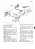
 Next
Next
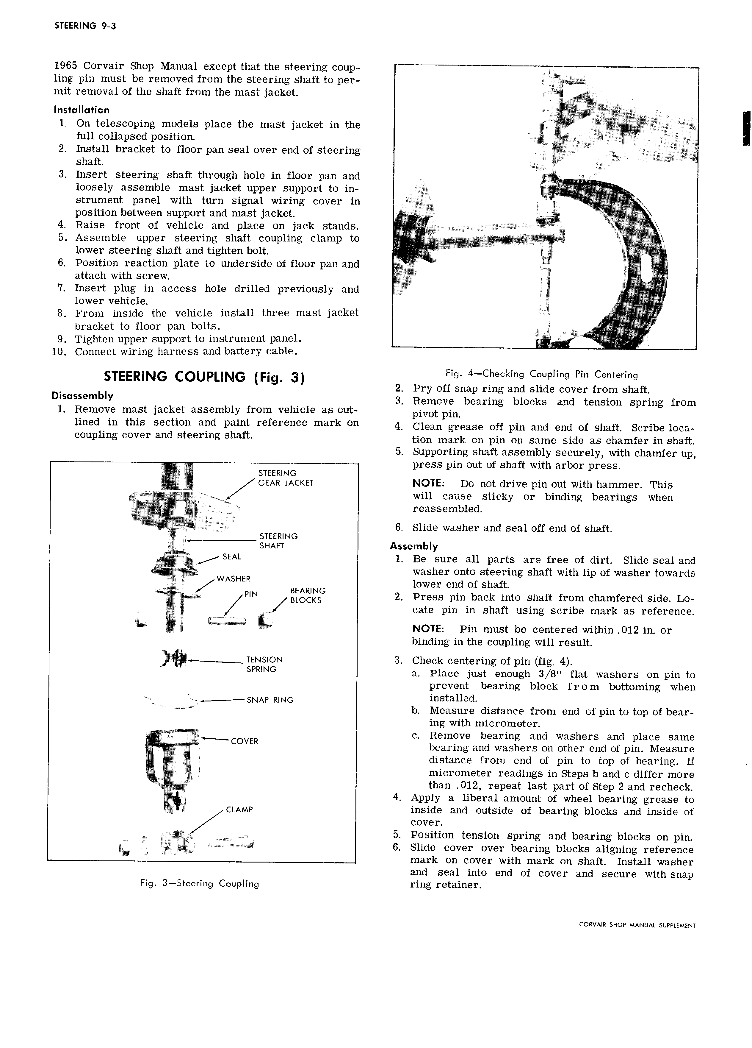
STEERING 9 3 1965 Corvair Shop Manual except that the steering coup ling pin must be removed from the steering shaft to per l A mit removal of the shaft from the mast jacket e H Inst ll ti0n r V 1 On telescoping models place the mast jacket in the if llllf ett I full collapsed position i j l 2 ijj 2 Install bracket to floor pan seal over end of steering I i V p 3 Insert steering shaft through hole in floor pan and loosely assemble mast jacket upper support to in l strument panel with turn signal wiring cover in S A i i position between support and mast jacket 4 Raise front of vehicle and place on jack stands t ae 5 Assemble upper steering shaft coupling clamp to l 4 i lower steering shaft and tighten bolt S A l ld lllll J U 6 Position reaction plate to underside of floor pan and fc attach with screw T P 7 Insert plug in access hole drilled previously and lower vehicle 6 A 8 From inside the vehicle install three mast jacket bracket to floor pan bolts V 9 Tighten upper support to instrument panel i P A 10 Connect wiring harness and battery cable Fig 4 Cl19Cl lt 1g COUplll 1g Pit C t l I lT1g 2 Pry off snap ring and slide cover from shaft Dl e blY 3 Remove bearing blocks and tension spring from 1 Remove mast jacket assembly from vehicle as out pivot pm 1i d in this Section ard Paint rererenee mark On 4 Clean grease off pin and end of shaft Scribe loca eeuplmg eever and eteermg Shaft tion mark on pin on same side as chamfer in shaft 5 Supporting shaft assembly securely with chamfer up STEERING press pin out of shaft with arbor press GEAR JACKET NOTE Do not drive pin out with hammer This will cause sticky or binding bearings when j gd reassembled j i STEERING 6 Slide washer and seal off end of shaft S V SEAL SHAFT Assembly jj Z 1 Be sure all parts are free of dirt Slide seal and WASHER Ivasher o utof sieefiing shaft with lip of washer towards f ower en o s a PIN giglgllglg 2 Press pin back into shaft from chamfered side Lo 6 cate pin in shaft using scribe mark as reference 2 Y gmmw L NOTE Pin must be centered within 012 in or binding in the coupling will result revision 3 Check centering of pin fig 4 M Z SPRNG a Place just enough 3 8 flat washers on pin to prevent bearing block from bottoming when es V r j SNAp RING installed b Measure distance from end of pin to top of bear ing with micrometer c Remove bearing and washers and place same V bearing and washers on other end of pin Measure distance from end of pin to top of bearing If micrometer readings in Steps b and c differ more i than 012 repeat last part of Step 2 and recheck 4 Apply a liberal amount of wheel bearing grease to CLAMP inside and outside of bearing blocks and inside of cover Vp 5 Position tension spring and bearing blocks on pin gh 1 W 6 Slide cover over bearing blocks aligning reference mark on cover with mark on shaft Install washer and seal into end of cover and secure with snap Fig 3 Steering Coupling ring I t ll1 l CORVAIR SHOP MANUAL SUPPLEMENT