Jeep Parts Wiki | Ford Parts Wiki
Home | Search | Browse | Marketplace | Messages | FAQ | Guest
|
Corvair Chassis Shop Manual Supplement December 1965 |
|
Prev

 Next
Next
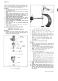
STEERING 9 2 CLAMP x 2 STEERING GEAR JACKET l SEAL BRACKET S I I r SHAFT ASM SEAT J GEAR ASM BEARING ASM Q SPACER All u L R P WASHER K f SPRING 6 L WASHER x it CLAM jj P I PLATE ASM E 16 cup LJ L X sou n 4 r Q xx EI I W SCREW Fig 2 Most Jcicket ond Coupiing MAST JACKET Fig 2 the steering shaft Removal 6 Remove the three directional signal retaining screws L Disconnect battery ground Cable and lift off switch retainer and housing 2 From inside the car remove the three bolts from the Assembly Non Telescoping mast jacket to floor pan bracket 1 Feed directional signal switch wiring through direc 3 Raise the front of the vehicle and drill a 1 1 8 tional signal housing and install housing onto mast diameter hole in the left front wheel splash shield jacket leaving switch hang to one side fig 1 2 Position directional signal switch retainer into hous 4 Remove steering coupling clamp bolt and nut ing and engage tangs on mast jacket with slots in 5 From under the vehicle remove the screw holding retainer the steering shaft stop plate to the floor pan and re 3 Align directional signal switch with housing and move stop plate retainer and loosely assemble with three screws 6 Lower vehicle and disconnect the two directional Then rotate the assembly clockwise to engage the signal wiring connectors from chassis harness tangs fully and tighten the screws 7 On Telescoping models place the mast jacket in the 4 Install E clip in groove in lower end of steering full collapsed position shaft Position clamp spring spacer lower bearing 8 While supporting the mast jacket remove the two and bearing seat over upper end of shaft and down attaching bolts at the upper mast jacket support against E clip 9 Pull the mast jacket up through the floor pan and 5 Insert steering shaft into bottom of mast jacket and out of the vehicle up through upper bearing and install upper bearing snap ring Dlmssembly N n Tgleswpmgi j 6 Position lower bearing seat and bearing into mast 1 Remove steering wheel as outlined in Section 9 of jacket and adjust clamp to allow 005 min to 030 the 1965 Corvair Shop Manual 2 max axial movement of steering shaft Tighten Remove directional signal lever and attaching screw 3 clamp bolt to 40 in lbs Us1ng a small screw driver or ice pick remove 7 Install steering wheel as outlined in Section 9 of the upper bearing snap ring from steering shaft 1965 Corvair Sho Manual 4 Slide steering shaft out bottom of mast jacket and p remove lower bearing seat lower bearing spacer Assembly und Disussembly Telescoping and clamp Assembly and disassembly procedures for the tele 5 If necessary pry the E clip from the lower end of scoping mast jacket remain the same as outlined in the CORVAIR SHOP MANUAL SUPPLEMENT