Jeep Parts Wiki | Ford Parts Wiki
Home | Search | Browse
|
Corvair Chassis Shop Manual Supplement December 1965 |
|
Prev

 Next
Next
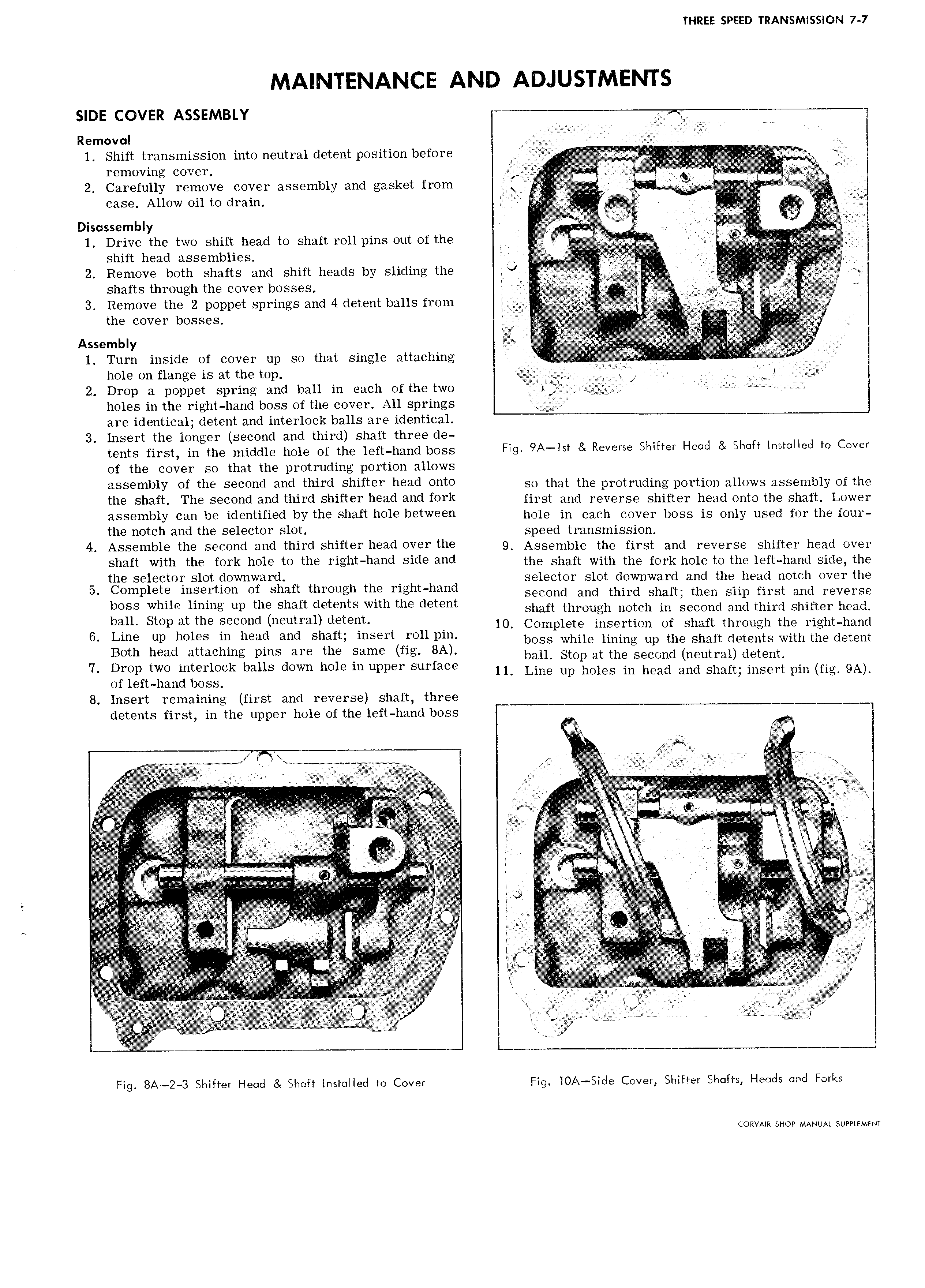
THREE SPEED TRANSMISSION 7 7 MAINTENANCE AND ADJUSTMENTS SIDE COVER ASSEMBLY s i Removal V 4 C I 1 Shift transmission into neutral detent position before V A I VV rI 7 sr 2 Carefully remove cover assembly and gasket from ji liVl i rr case Allow oil to drain i i A Y v g Di mbiY M y 1 Drive the two shift head to shaft ren pins out of the I shift head assemblies i e I V 2 Remove both shafts and shift heads by siidihg the O V O g i ee shafts through the cover bosses I e at W 3 Remove the 2 poppet springs and 4 detent balls from the cover bosses A E t O sll A Y x it 1 Turn inside of cover up so that single attaching Q hole on flange is at the top X 5 2 Drop a poppet spring and ball in each of the two gsi X if M holes in the right hand boss of the cover All springs are identical detent and interlock balls are identical 3 Insert the longer second and third shaft three de ents first in the middle hOi gf thO iOft h md bOSS Fig 9A lst Reverse Shifter Head Shdft ihstelleel to Cover of the cover so that the protruding portion allows assembly of the second and third Shiftef h 3d O tO so that the protruding portion allows assembly of the the shaft The seeohd and third shifter head and fork first and reverse shifter head onto the shaft Lower assembly can be identified by the shaft hole between OOIQ in Gam OOVOT OOSS is Only used Oy the OO the notch and the selector slot Speerd t1 mSmiSSiOn 4 Assemble the seeohd and third shifter head over the 9 Assemble the first ahd reverse shifter head ever shaft with the fork hole to the right hand side and the shaft with the fork hole to the iert hahd side the the selector slot downward selector slot downward and the head notch over the 5 g p5 1p1 rt1On Ofh Shiftfttgrguih mihrtfhtgtiani second and third shaft then slip first and reverse ban Sm tilgmg up di S EE Dade Stwl 9 G en shaft through notch in second and third shifter head 6 Lin u psd 9 serie dueudm h gm t H 10 Complete insertion of shaft through the right hand Bot hgad Sim d an S S1 WSH EO boss while lining up the shaft detents with the detent 7 Drop two in ierloc1li1gbaIii Sd wxi ho Iuqgperlgurface bam Stop at the Second neutral detgnh S ll Line up holes in head and shaft insert pin fig 9A of left hand boss 8 Insert remaining first and reverse shaft three detents first in the upper hole of the left hand boss V A s i rt er i ii i I i i i i i it r g U A ry r 1 t rvr is e i i it t t I I I i i rt iiisirrs i e i ii z i i s i i r C r r 1 J 2 i i i i t A TW r r 2 sii t r L r ii rti te t i i t r rt esir s i i i e i i ri r v S O I i e we i i f er e I is r i rf r j e ret g t ri ri rr y rs rt i r rr ti ii tj i i iite f s fiif ti elri s erse eirr g Qe f i3 F gs ss ga ie e s 1 ff W e Fig 8A 2 3 Shifter Head 8 Shaft installed to Cover Fig iOA Side Cover Shifter Straits Heads and Forks CORVAIR SHOP MANUAL SUPPLEMENT

 Next
Next