Jeep Parts Wiki | Ford Parts Wiki
Home | Search | Browse
|
Corvair Chassis Shop Manual Supplement December 1965 |
|
Prev

 Next
Next
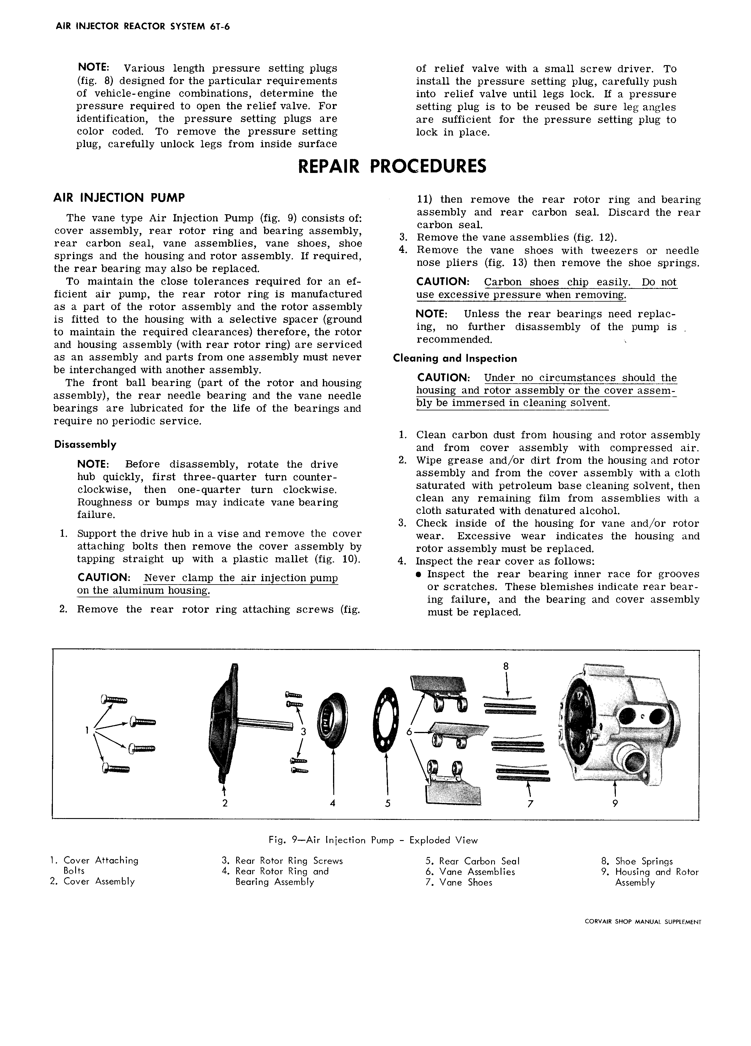
AIR INJECTOR REACTOR SYSTEM 6T 6 NOTE Various length pressure setting plugs of relief valve with a small screw driver T0 fig 8 designed for the particular requirements install the pressure setting plug carefully push of vehicle engine combinations determine the into relief valve until legs lock If a pressure pressure required to open the relief valve For setting plug is to be reused be sure leg angles identification the pressure setting plugs are are sufficient for the pressure setting plug to color coded To remove the pressure setting lock in place plug carefully unlock legs from inside surface REPAIR PROCEDURES AIR INJECTION PUMP 11 then remove the rear rotor ring and bearing The vane type Air Injection Pump fig 9 consists of assgmbly Tad mar carbon Seal Dlscard the mar cover assembly rear rotor ring and bearing assembly 3 ng eSt vane assemblies fi 12 rear carbon seal vane assemblies vane shoes shoe 4 Remove the Vane Shoes Withgeweeeers Or needle springs and the housing and rotor assembly If required the rear bearing may also be replaced nose pliers fig 13 then remove the shoe springs To maintain the close tolerances required for an ef CAUTION Carbon shoes chip easily Do not ficient air pump the rear rotor ring is manufactured use excessive pressure when removing as a part of the rotor assembly and the rotor assembly is fitted to the housing with a selective spacer ground NOTE Unless th rear bearmgs need mph to maintain the required clearances therefore the rotor mg no further dtsassembly Of the pump IS and housing assembly with rear rotor ring are serviced recommended as an assembly and parts from one assembly must never Clgqning und Inspection be interchanged with another assembly The front ball bearing part of the rotor and housing CAUTION assembly the rear needle bearing and the vane needle bearings are lubricated for the life of the bearings and require no periodic service 1 Clean carbon dust from housing and rotor assembly D blY and from cover assembly with compressed air NOTE Before disassembly rotate the drive 2 Wipe grease and or dirt from the housingiand rotor hub quickly first three queI teI turn eO mter assembly and from the cover assembly with a cloth eleekwisee then One que1 teI turn eleekwieel saturated with petroleum base cleaning solventethen Reuehneee Or bumps may indicate Vane bearing clean any remaining film from assemblies with a fei1m e cloth saturated with denatured alcohol 3 Check inside of the housing for vane and or rotor 1 Sumwrt the drive hub in a vise and remcwe the v r wear Excessive wear indicates me housing and attaching bolts then remove the cover assembly by rotor assembly must bg r p1aCed tapping Straight up with a plastic mallet fig 10 4 Inspect the rear cover as renews CAUTION Neve clamp the eh injection pump Inspect the rear bearing inner race for grooves On the e1umi or scratches These blemishes indicate rear bear ing failure and the bearing and cover assembly 2 Remove the rear rotor ring attaching screws fig must be replaced 8 l I I A I I Rm i o l r 3 6 g te Q gnu I I H e e l 2 4 5 1 7 9 Fig 9 Air lniection Pump Exploded View l Cover Attaching 3 Rear Rotor Ring Screws 5 Rear Carbon Seal 8 Shoe Springs Bolts 4 Rear Rotor Ring and 6 Vane Assemblies 9 Housing and Rotor 2 Cover Assembly Bearing Assembly 7 Vane Shoes Assembly CORVAIR SHOP MANUAL SUPPLEMENT

 Next
Next