Jeep Parts Wiki | Ford Parts Wiki
Home | Search | Browse
Prev

 Next
Next
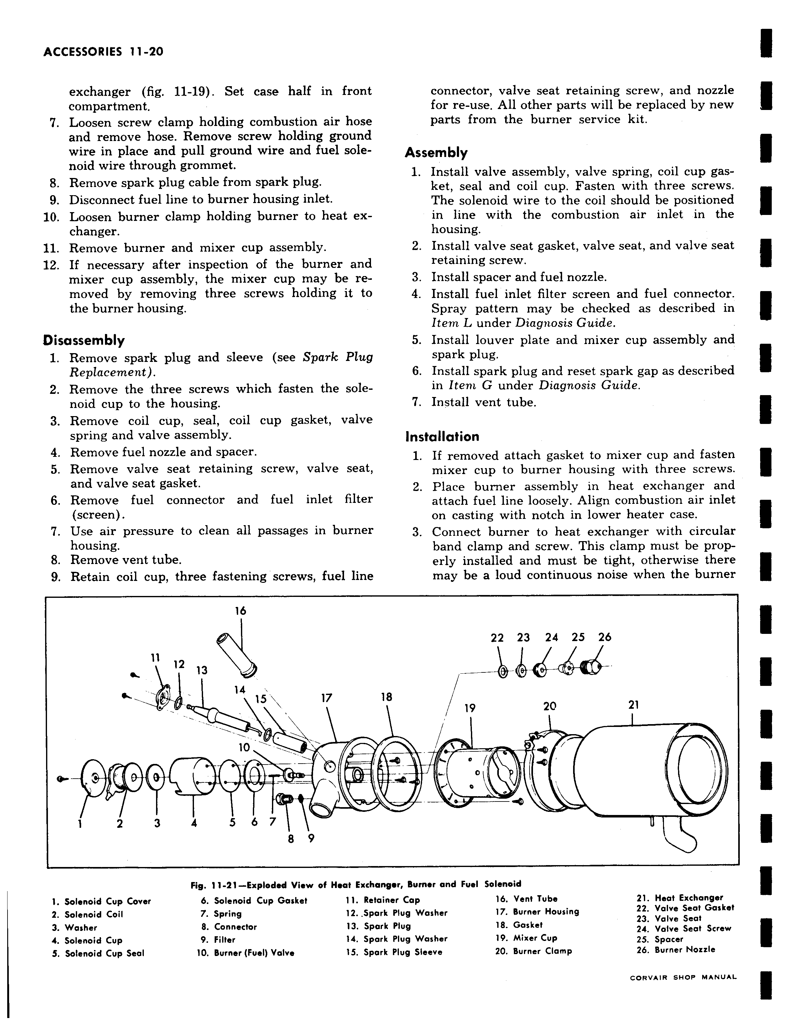
exchanger fig 11 19 Set case half in front compartment 7 Loosen screw clamp holding combustion air hose and remove hose Remove screw holding ground wire in place and pull ground wire and fuel solenoid wire through grommet 8 Remove spark plug cable from spark plug 9 Disconnect fuel line to burner housing inlet 10 Loosen burner clamp holding burner to heat exchanger 11 Remove burner and mixer cup assembly 12 If necessary after inspection of the burner and mixer cup assembly the mixer cup may be removed by removing three screws holding it to the burner housing Disassembly 1 Remove spark plug and sleeve see Spark Plug Replacement 2 Remove the three screws which fasten the solenoid cup to the housing 3 Remove coil cup seal coil cup gasket valve spring and valve assembly 4 Remove fuel nozzle and spacer 5 Remove valve seat retaining screw valve seat and valve seat gasket 6 Remove fuel connector and fuel inlet filter screen 7 Use air pressure to clean all passages in burner housing 8 Remove vent tube 9 Retain coil cup three fastening screws fuel line 16 11 12 e 1 eeJJ3 14 15 s 17 10 h 1 2 3 4 5 6 7 1 8 9 Fig 11 21 Exploded View of Heat Excha 1 Solenoid Cup Cover 6 Solenoid Cup Gasket 11 Retc 2 Solenoid Coil 7 Spring 12 Spa 3 Washer 8 Connector 13 Spa 4 Solenoid Cup 9 Filter 14 Spa S Solenoid Cup Seal 10 Burner Fuel Valve 15 Spa connector valve seat retaining screw and nozzle for re use All other parts will be replaced by new parts from the burner service kit Assembly 1 Install valve assembly valve spring coil cup gasket seal and coil cup Fasten with three screws The solenoid wire to the coil should be positioned in line with the combustion air inlet in the housing 2 Install valve seat gasket valve seat and valve seat retaining screw 3 Install spacer and fuel nozzle 4 Install fuel inlet filter screen and fuel connector Spray pattern may be checked as described in Item L under Diagnosis Guide 5 Install louver plate and mixer cup assembly and spark plug 6 Install spark plug and reset spark gap as described in Item G under Diagnosis Guide 7 Install vent tube Installation 1 If removed attach gasket to mixer cup and fasten mixer cup to burner housing with three screws 2 Place burner assembly in heat exchanger and attach fuel line loosely Align combustion air inlet on casting with notch in lower heater case 3 Connect burner to heat exchanger with circular band clamp and screw This clamp must be properly installed and must be tight otherwise there may be a loud continuous noise when the burner 22 23 24 25 26 18 19 20 21 0 nger Burner and Fuel Solenoid iner Cap 16 Vent Tube 21 Heat Exchanger k Plug Washer 17 Burner Housing 22 Valve Seat Gasket k Plug 18 Gasket 23 Valve Seat 24 Valve Seat Screw k Plug Washer 19 Mixer Cup 25 Spacer k Plug Sleeve 20 Burner Clamp 26 Burner Nozzle

 Next
Next