Jeep Parts Wiki | Ford Parts Wiki
Home | Search | Browse
Prev

 Next
Next
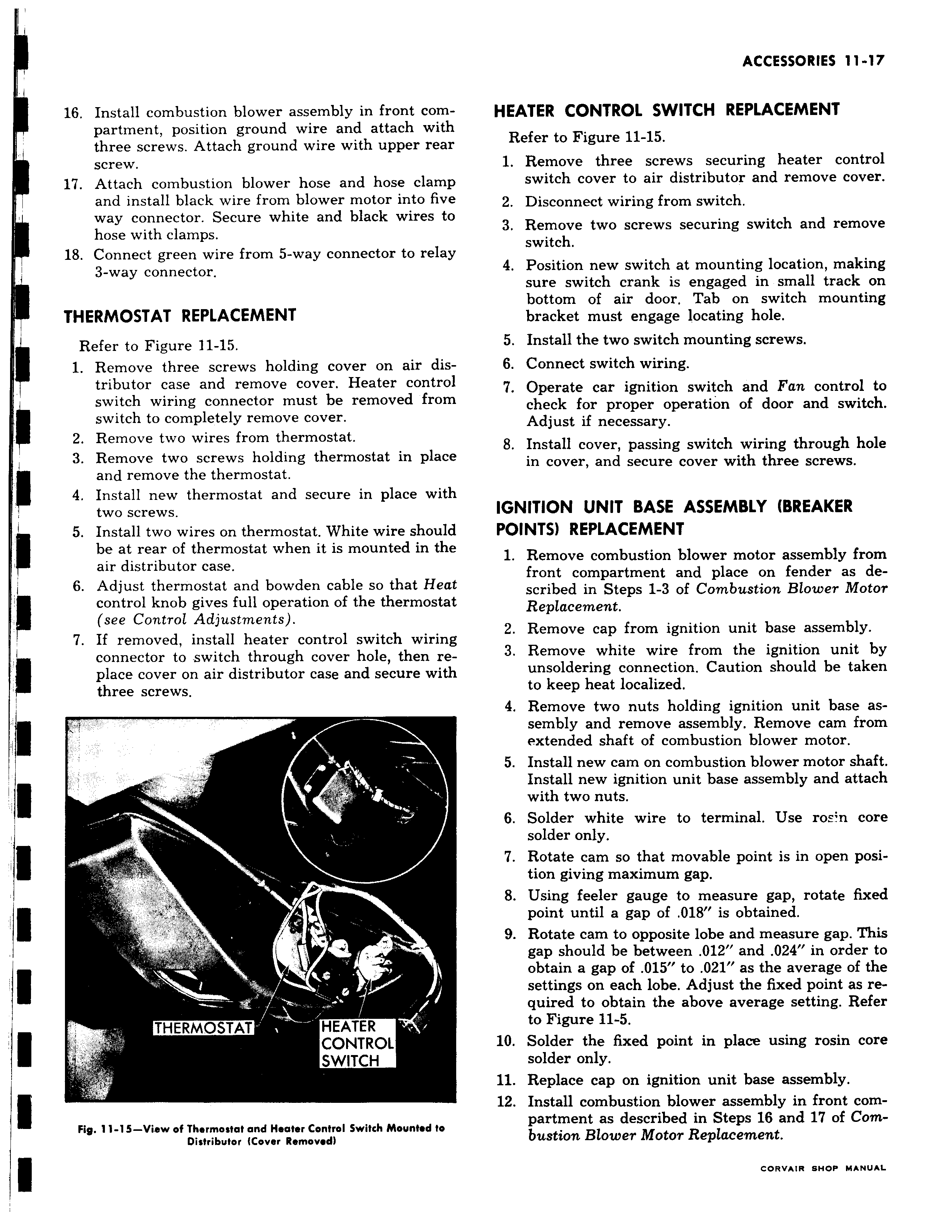
i I 16 Install combustion blower assembly in front compartment position ground wire and attach with three screws Attach ground wire with upper rear screw 17 Attach combustion blower hose and hose clamr and install black wire from blower motor into five way connector Secure white and black wires tc hose with clamps 18 Connect green wire from 5 way connector to relay 3 way connector THERMOSTAT REPLACEMENT Refer to Figure 11 15 1 Remove three screws holding cover on air distributor case and remove cover Heater control switch wiring connector must be removed frorr switch to completely remove cover 2 Remove two wires from thermostat 3 Remove two screws holding thermostat in place and remove the thermostat 4 Install new thermostat and secure in place witr two screws I 5 Install two wires on thermostat White wire shoulc be at rear of thermostat when it is mounted in the air distributor case 6 Adjust thermostat and bowden cable so that Hea control knob gives full operation of the thermostal see Control Adjustments 7 If removed install heater control switch wirin connector to switch through cover hole then replace cover on air distributor case and secure witl three screws k 1 THERMOSTAT HEATER CONTROL SWITCH Fig 11 15 View of Thermostat and Hooter Control Switch Mounted to Distributor Mover Removed HEATER CONTROL SWITCH REPLACEMENT Refer to Figure 11 15 1 Remove three screws securing heater control switch cover to air distributor and remove cover 2 Disconnect wiring from switch 3 Remove two screws securing switch and remove switch 4 Position new switch at mounting location making sure switch crank is engaged in small track on bottom of air door Tab on switch mounting bracket must engage locating hole 5 Install the two switch mounting screws 6 Connect switch wiring 7 Operate car ignition switch and Fan control to check for proper operation of door and switch Adjust if necessary 8 Install cover passing switch wiring through hole in cover and secure cover with three screws IGNITION UNIT BASE ASSEMBLY BREAKER POINTS REPLACEMENT 1 Remove combustion blower motor assembly from front compartment and place on fender as described in Steps 1 3 of Combustion Blower Motor Replacement 2 Remove cap from ignition unit base assembly 3 Remove white wire from the ignition unit by unsoldering connection Caution should be taken to keep heat localized 4 Remove two nuts holding ignition unit base assembly and remove assembly Remove cam from extended shaft of combustion blower motor 5 Install new cam on combustion blower motor shaft Install new ignition unit base assembly and attach with two nuts 6 Solder white wire to terminal Use ros n core solder only 7 Rotate cam so that movable point is in open position giving maximum gap 8 Using feeler gauge to measure gap rotate fixed point until a gap of 018 is obtained 9 Rotate cam to opposite lobe and measure gap This gap should be between 012 and 024 in order to obtain a gap of 015 to 021 as the average of the settings on each lobe Adjust the fixed point as required to obtain the above average setting Refer to Figure 11 5 10 Solder the fixed point in place using rosin core solder only 11 Replace cap on ignition unit base assembly 12 Install combustion blower assembly in front compartment as described in Steps 16 and 17 of Combustion Blower Motor Replacement

 Next
Next