Jeep Parts Wiki | Ford Parts Wiki
Home | Search | Browse
Prev

 Next
Next
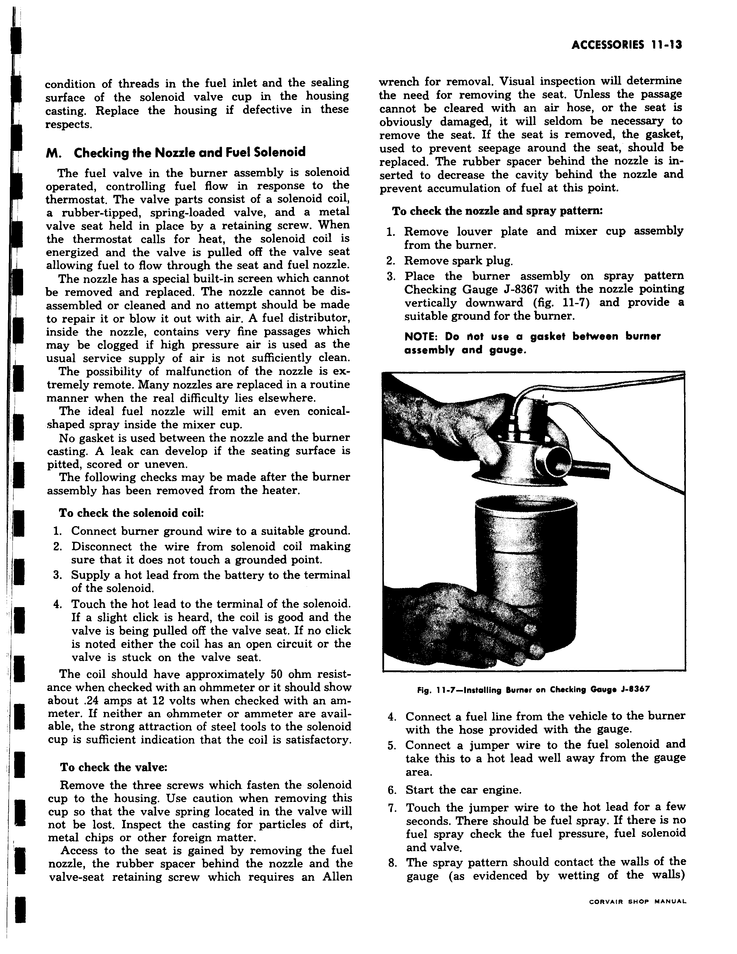
condition of threads in the fuel inlet and the sealing surface of the solenoid valve cup in the housing casting Replace the housing if defective m these respects M Checking the Nozzle and Fuel Solenoid The fuel valve in the burner assembly is solenoid 1 operated controlling fuel flow in response to the thermostat The valve parts consist of a solenoid coil a rubber tipped spring loaded valve and a metal valve seat held in place by a retaining screw When the thermostat calls for heat the solenoid coil is energized and the valve is pulled off the valve seat I allowing fuel to flow through the seat and fuel nozzle The nozzle has a special built in screen which cannot be removed and replaced The nozzle cannot be disassembled or cleaned and no attempt should be made to repair it or blow it out with air A fuel distributor f inside the nozzle contains very fine passages which may be clogged if high pressure air is used as the usual service supply of air is not sufficiently clean The possibility of malfunction of the nozzle is extremely remote Many nozzles are replaced in a routine manner when the real difficulty lies elsewhere The ideal fuel nozzle will emit an even conicalshaped spray inside the mixer cup No gasket is used between the nozzle and the burner casting A leak can develop if the seating surface is pitted scored or uneven The following checks may be made after the burner assembly has been removed from the heater To check the solenoid coil 1 Connect burner ground wire to a suitable ground 2 Disconnect the wire from solenoid coil making sure that it does not touch a grounded point 3 Supply a hot lead from the battery to the terminal of the solenoid 4 Touch the hot lead to the terminal of the solenoid If a slight click is heard the coil is good and the valve is being pulled off the valve seat If no click is noted either the coil has an open circuit or the valve is stuck on the valve seat The coil should have approximately 50 ohm resistance when checked with an ohmmeter or it should show about 24 amps at 12 volts when checked with an am I meter If neither an ohmmeter or ammeter are available the strong attraction of steel tools to the solenoid cup is sufficient indication that the coil is satisfactory To check the valve Remove the three screws which fasten the solenoid not to the housing Use caution when removing this cup so that the valve spring located in the valve will not be lost Inspect the casting for particles of dirt metal chips or other foreign matter Access to the seat is gained by removing the fuel nozzle the rubber spacer behind the nozzle and the valve seat retaining screw which requires an Allen wrench for removal Visual inspection will determine the need for removing the seat Unless the passage cannot be cleared with an air hose or the seat is obviously damaged it will seldom be necessary to remove the seat If the seat is removed the gasket used to prevent seepage around the seat should be replaced The rubber spacer behind the nozzle is inserted to decrease the cavity behind the nozzle and prevent accumulation of fuel at this point To check the nozzle and spray pattern 1 Remove louver plate and mixer cup assembly from the burner 2 Remove spark plug 3 Place the burner assembly on spray pattern Checking Gauge J 8367 with the nozzle pointing vertically downward fig 11 7 and provide a suitable ground for the burner NOTE Do not use a gasket between burner assembly and gauge i Fig 11 7 Installing bumer on Checking Gauge J B367 4 Connect a fuel line from the vehicle to the burner with the hose provided with the gauge 5 Connect a jumper wire to the fuel solenoid and take this to a hot lead well away from the gauge area 6 Start the car engine 7 Touch the jumper wire to the hot lead for a few seconds There should be fuel spray If there is no fuel spray check the fuel pressure fuel solenoid and valve 8 The spray pattern should contact the walls of the gauge as evidenced by wetting of the walls

 Next
Next