Jeep Parts Wiki | Ford Parts Wiki
Home | Search | Browse
Prev

 Next
Next
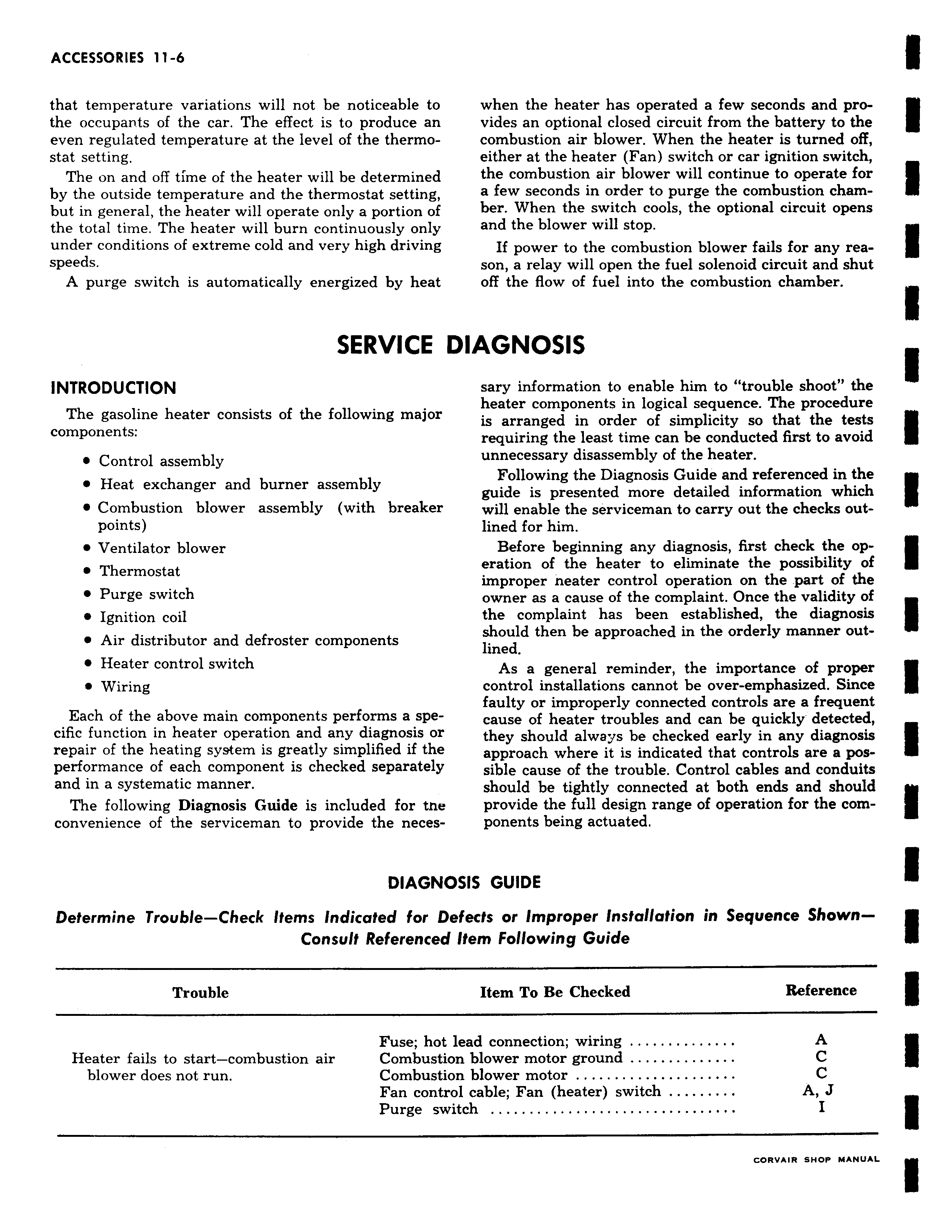
that temperature variations will not be noticeable to the occupants of the car The effect is to produce an even regulated temperature at the level of the thermostat setting The on and off time of the heater will be determined by the outside temperature and the thermostat setting but in general the heater will operate only a portion of the total time The heater will burn continuously only under conditions of extreme cold and very high driving speeds A purge switch is automatically energized by heat SERVICE I INTRODUCTION The gasoline heater consists of the following major components Control assembly Heat exchanger and burner assembly Combustion blower assembly with breaker points Ventilator blower Thermostat Purge switch Ignition coil Air distributor and defroster components Heater control switch Wiring Each of the above main components performs a specific function in heater operation and any diagnosis or repair of the heating system is greatly simplified if the performance of each component is checked separately and in a systematic manner The following Diagnosis Guide is included for the convenience of the serviceman to provide the necesDIAGNC Determine Trouble Check Items Indicated for De Consult Referenced Trouble Fuse hot Heater fails to start combustion air Combustic blower does not run Combustic Fan contr Purge sw when the heater has operated a few seconds and provides an optional closed circuit from the battery to the combustion air blower When the heater is turned off either at the heater Fan switch or car ignition switch the combustion air blower will continue to operate for a few seconds in order to purge the combustion chamber When the switch cools the optional circuit opens and the blower will stop If power to the combustion blower fails for any reason a relay will open the fuel solenoid circuit and shut off the flow of fuel into the combustion chamber IAGNOSIS sary information to enable him to trouble shoot the heater components in logical sequence The procedure is arranged in order of simplicity so that the tests requiring the least time can be conducted first to avoid unnecessary disassembly of the heater Following the Diagnosis Guide and referenced in the guide is presented more detailed information which will enable the serviceman to carry out the checks outlined for him Before beginning any diagnosis first check the operation of the heater to eliminate the possibility of improper neater control operation on the part of the owner as a cause of the complaint Once the validity of the complaint has been established the diagnosis should then be approached in the orderly manner outlined As a general reminder the importance of proper control installations cannot be over emphasized Since faulty or improperly connected controls are a frequent cause of heater troubles and can be quickly detected they should always be checked early in any diagnosis approach where it is indicated that controls are a possible cause of the trouble Control cables and conduits should be tightly connected at both ends and should provide the full design range of operation for the components being actuated iSIS GUIDE fects or Improper Installation in Sequence ShownItem Following Guide Item To Be Checked Reference lead connection wiring A n blower motor ground C n blower motor C il cable Fan heater switch A J tch I RVAIR SNMP MANUAL

 Next
Next