Jeep Parts Wiki | Ford Parts Wiki
Home | Search | Browse
Prev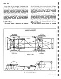
 Next
Next
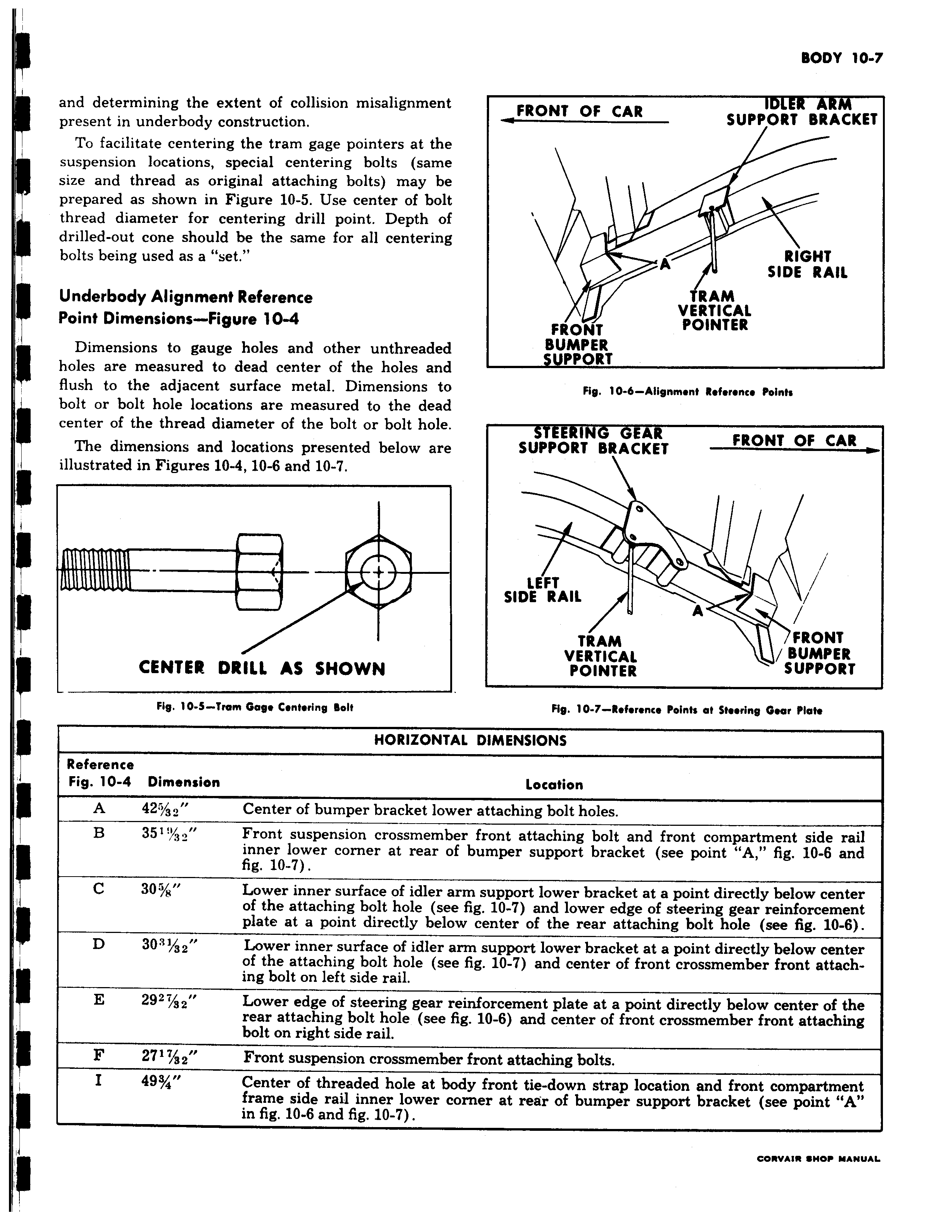
and determining the extent of collision misalignment present in underbody construction To facilitate centering the tram gage pointers at the suspension locations special centering bolts same size and thread as original attaching bolts may be prepared as shown in Figure 10 5 Use center of bolt thread diameter for centering drill point Depth of drilled out cone should be the same for all centering bolts being used as a set Underbody Alignment Reference Point Dimensions Figure 10 4 Dimensions to gauge holes and other unthreaded holes are measured to dead center of the holes and flush to the adjacent surface metal Dimensions to bolt or bolt hole locations are measured to the dead center of the thread diameter of the bolt or bolt hole The dimensions and locations presented below are illustrated in Figures 10 4 10 6 and 10 7 CENTER DRILL AS SHOWN Fig 10 S Trom Gage Centering Bolt HORIZONL Reference Fig 10 4 Dimension A 42 Center of bumper bracket lom B 351 3 Front suspension crossmemb inner lower corner at rear o fig 10 7 C 30 s Lower inner surface of idler a of the attaching bolt hole se4 plate at a point directly bele D 30 1 3 2 Lower inner surface of idler z of the attaching bolt hole sei ing bolt on left side rail E 292 21P Lower edge of steering gear r rear attaching bolt hole see 1 bolt on right side rail F 2717 g 2 Front suspension crossmembe I 49s Center of threaded hole at b frame side rail inner lower c in fig 10 6 and fig 10 7 r FRONT OF CAR IDLER ARM SUPPORT BRACKET A RIGHT SIDE RR AII RAM VERTICAL FRONT POINTER BUMPER SUPPORT Fig 10 6 Alignment Reference Points STEERING GEAR FRONT OF CAR SUPPORT BRACKET 0 0 LEFT SIDE RAIL Q w A TRAM FRONT VERTICAL BUMPER POINTER SUPPORT Fig 10 7 Refer9rice Points at Steering Gear Plot 1L DIMENSIONS Location er attaching bolt holes er front attaching bolt and front compartment side rail f bumper support bracket see point A fig 10 6 and rm support lower bracket at a point directly below center a fig 10 7 and lower edge of steering gear reinforcement w center of the rear attaching bolt hole see fig 10 6 rm support lower bracket at a point directly below center fig 10 7 and center of front crossmember front attacheinforcement plate at a point directly below center of the ig 10 6 and center of front crossmember front attaching r front attaching bolts dy front tie down strap location and front compartment i rner at rear of bumper support bracket see point A eowwIw SHOP MANUAL