Jeep Parts Wiki | Ford Parts Wiki
Home | Search | Browse
Prev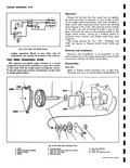
 Next
Next
5096576
5096576
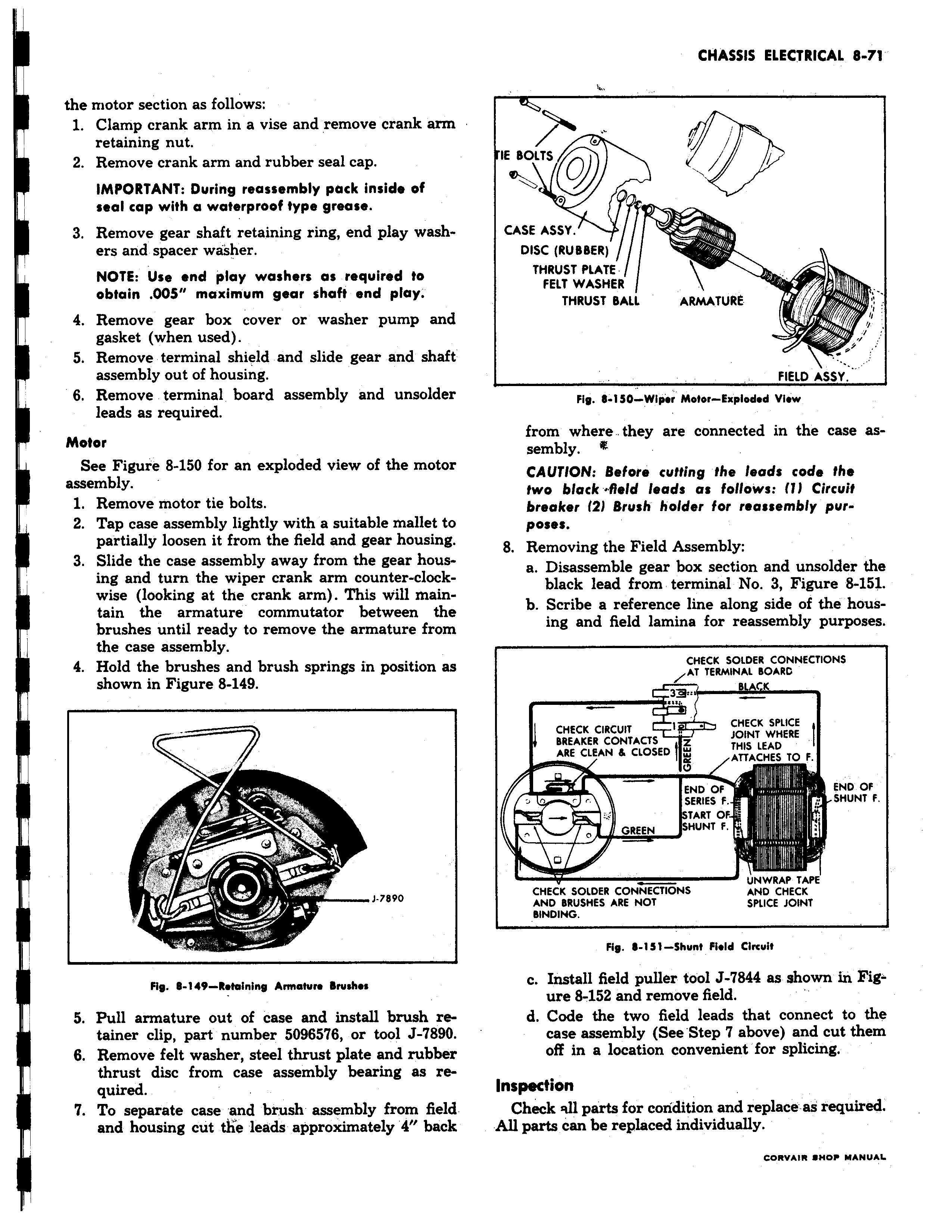
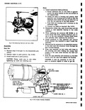
the motor section as follows 1 Clamp crank arm in a vise and remove crank arm retaining nut 2 Remove crank arm and rubber seal cap IMPORTANT During reassembly pack inside of seal cap with a waterproof type grease 3 Remove gear shaft retaining ring end play washers and spacer washer i NOTE Use end play washers as required to obtain 005 maximum gear shaft end play 4 Remove gear box cover or washer pump and gasket when used 5 Remove terminal shield and slide gear and shah assembly out of housing 6 Remove terminal board assembly and unsoldei leads as required Motor See Figure 8 150 for an exploded view of the motoi assembly 1 Remove motor tie bolts 2 Tap case assembly lightly with a suitable mallet tc partially loosen it from the field and gear housing 3 Slide the case assembly away from the gear hous I ing and turn the wiper crank arm counter clock wise looking at the crank arm This will main tain the armature commutator between the brushes until ready to remove the armature from the case assembly 4 Hold the brushes and brush springs in position a shown in Figure 8 149 J 7890 I Fig 8 149 Retaining Armature Brushes 5 Pull armature out of case and install brush re tainer clip part number 5096576 or tool J 7890 6 Remove felt washer steel thrust plate and rubbei thrust disc from case assembly bearing as rL quired 7 To separate case and brush assembly from fielc and housing cut the leads approximately 4 bacl v IE BOLTS CASE ASSY DISC RUBBER THRUST PLATE FELT WASHER I THRUST BAIL ARMATURE FIELD ASSY from where they are connected in the case assembly t CAUTION Before cutting the leads code the two black field leads as follows 1 Circuit breaker 2 Brush holder for reassembly purposes 8 Removing the Field Assembly a Disassemble gear box section and unsolder the black lead from terminal No 3 Figure 8 151 b Scribe a reference line along side of the housing and field lamina for reassembly purposes CHECK SOLDER CONNECTIONS AT TERMINAL BOARD c 3 aCHECK CIRCUIT 1 CHECK SPLICE BREAKER CONTACTS Z JOINT WHERE ARE CLEAN 6 CLOSED W THIS LEAD ATTACHES TO F O END OF END OF SERIES F SHUNT F START OF v 0 V GREEN SHUNT F D UNWRAP TAPE CHECK SOLDER CONNECTIONS AND CHECK AND BRUSHES ARE NOT SPLICE JOINT BINDING Fig 6 151 Shunt Field Circuit c Install field puller fool J 7844 as shown in Fig ure 8 152 and remove field d Code the two field leads that connect to the case assembly See Step 7 above and cut them off in a location convenient for splicing Inspection Check sill parts for condition and replace as required All parts can be replaced individually CORVALR SHOP MANUAL