Jeep Parts Wiki | Ford Parts Wiki
Home | Search | Browse
Prev
 Next
Next
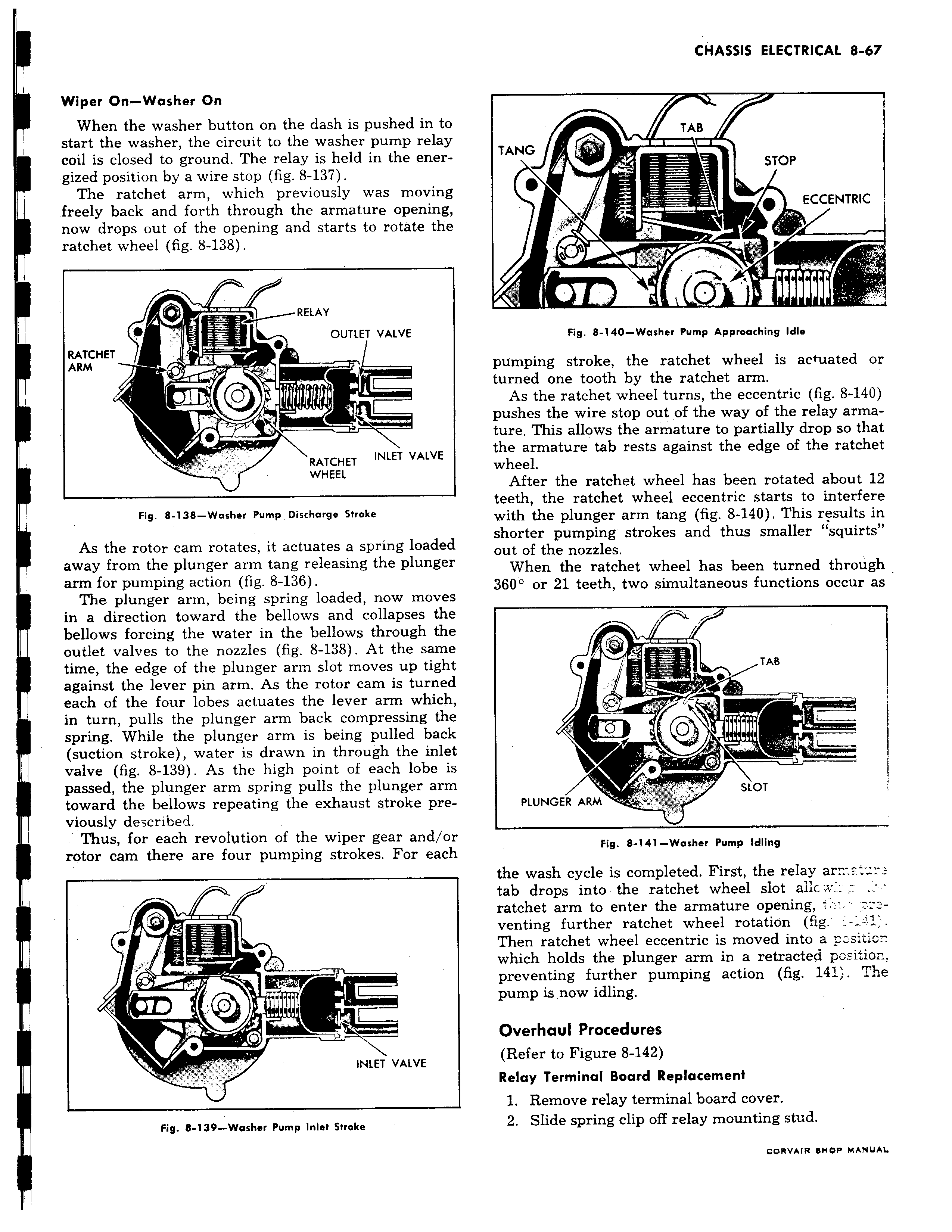
i Wiper On Washer On When the washer button on the dash is pushed in tc start the washer the circuit to the washer pump rela3 coil is closed to ground The relay is held in the energized position by a wire stop fig 8 137 The ratchet arm which previously was movin freely back and forth through the armature opening now drops out of the opening and starts to rotate the ratchet wheel fig 8 138 RELAY OUTLET VALVE RATCHET ARM e a RATCHET INLET VALVE WHEEL Fig 8 138 Washer Pump Discharge Stroke As the rotor cam rotates it actuates a spring loaded away from the plunger arm tang releasing the plungei arm for pumping action fig 8 136 The plunger arm being spring loaded now move in a direction toward the bellows and collapses thE bellows forcing the water in the bellows through the outlet valves to the nozzles fig 8 138 At the same time the edge of the plunger arm slot moves up tighl against the lever pin arm As the rotor cam is turned each of the four lobes actuates the lever arm which in turn pulls the plunger arm back compressing the spring While the plunger arm is being pulled back suction stroke water is drawn in through the inlel valve fig 8 139 As the high point of each lobe i passed the plunger arm spring pulls the plunger arrr toward the bellows repeating the exhaust stroke previously described I Thus for each revolution of the wiper gear and o1 rotor cam there are four pumping strokes For eacr I e w INLET VALVE y Fig 8 139 Washer Pump Inlet Stroke I TAB TANG i STOP ECCENTRIC Fig 8 140 Washer Pump Approaching Idle pumping stroke the ratchet wheel is actuated or turned one tooth by the ratchet arm As the ratchet wheel turns the eccentric fig 8 140 pushes the wire stop out of the way of the relay armature This allows the armature to partially drop so that the armature tab rests against the edge of the ratchet wheel After the ratchet wheel has been rotated about 12 teeth the ratchet wheel eccentric starts to interfere with the plunger arm tang fig 8 140 This results in shorter pumping strokes and thus smaller squirts out of the nozzles When the ratchet wheel has been turned through 3601 or 21 teeth two simultaneous functions occur as TAB O II I SLOT PLUNGER ARM Fig 8 141 Washer Pump Idling the wash cycle is completed First the relay ar v tab drops into the ratchet wheel slot aiic s ratchet arm to enter the armature opening venting further ratchet wheel rotation fig Then ratchet wheel eccentric is moved into a sitiowhich holds the plunger arm in a retracted position preventing further pumping action fig 141 The pump is now idling Overhaul Procedures Refer to Figure 8 142 Relay Terminal Board Replacement 1 Remove relay terminal board cover 2 Slide spring clip off relay mounting stud CORVAIR SHOP MANUAL