Jeep Parts Wiki | Ford Parts Wiki
Home | Search | Browse | Marketplace | Messages | FAQ | Guest
Prev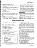
 Next
Next
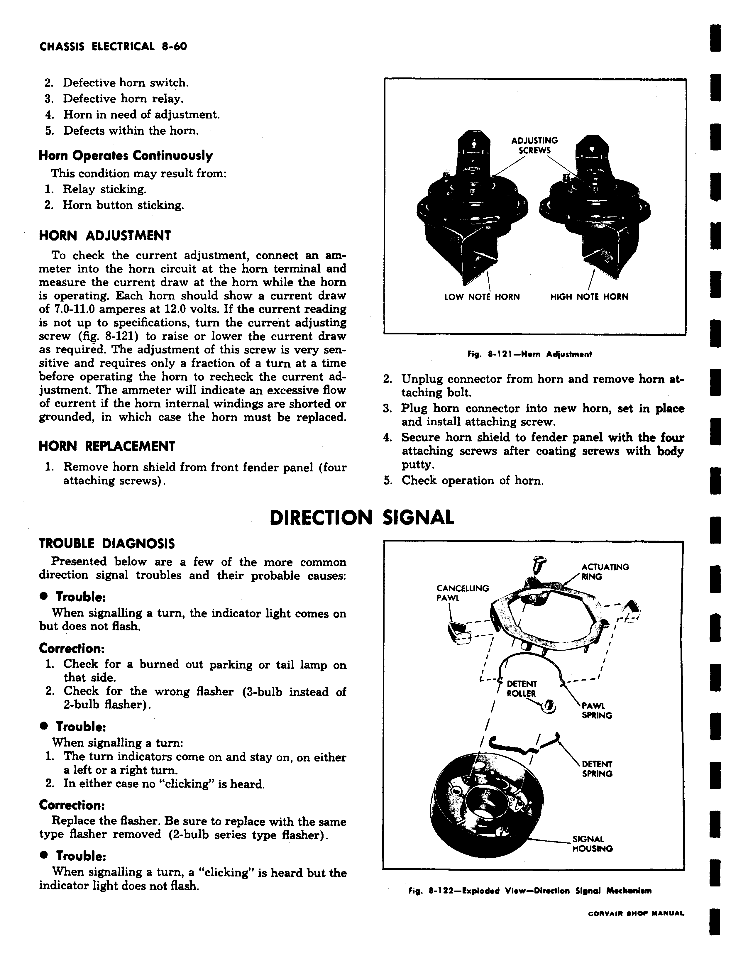
2 Defective horn switch 3 Defective horn relay 4 Horn in need of adjustment 5 Defects within the horn Horn Operates Continuously This condition may result from 1 Relay sticking 2 Horn button sticking HORN ADJUSTMENT To check the current adjustment connect an ammeter into the horn circuit at the horn terminal and measure the current draw at the horn while the horn is operating Each horn should show a current draw of 7 0 11 0 amperes at 12 0 volts If the current reading is not up to specifications turn the current adjusting screw fig 8 121 to raise or lower the current draw as required The adjustment of this screw is very sensitive and requires only a fraction of a turn at a time before operating the horn to recheck the current adjustment The ammeter will indicate an excessive flow of current if the horn internal windings are shorted or grounded in which case the horn must be replaced HORN REPLACEMENT 1 Remove horn shield from front fender panel four attaching screws DIRECTIO TROUBLE DIAGNOSIS Presented below are a few of the more common direction signal troubles and their probable causes Trouble When signalling a turn the indicator light comes on but does not flash Correction 1 Check for a burned out parking or tail lamp on that side 2 Check for the wrong flasher 3 bulb instead of 2 bulb flasher 0 Trouble When signalling a turn 1 The turn indicators come on and stay on on either a left or a right turn 2 In either case no clicking is heard Correction Replace the flasher Be sure to replace with the same type flasher removed 2 bulb series type flasher Trouble When signalling a turn a clicking is heard but the indicator light does not flash ADJUSTING SC STING REWS LOW NOTE HORN HIGH NOTE HORN Fig 8 121 Horn Adjustment 2 Unplug connector from horn and remove horn attaching bolt 3 Plug horn connector into new horn set in place and install attaching screw 4 Secure horn shield to fender panel with the four attaching screws after coating screws with body putty 5 Check operation of horn N SIGNAL ACTUATING RING CANCELLING PAWL F I DETENT ROLLER M PAWL SPRING DETENT SPRING a SIGNAL MOUSING Fig 6 142 Explodod View Direction Signal Mechanism