Jeep Parts Wiki | Ford Parts Wiki
Home | Search | Browse
Prev
 Next
Next
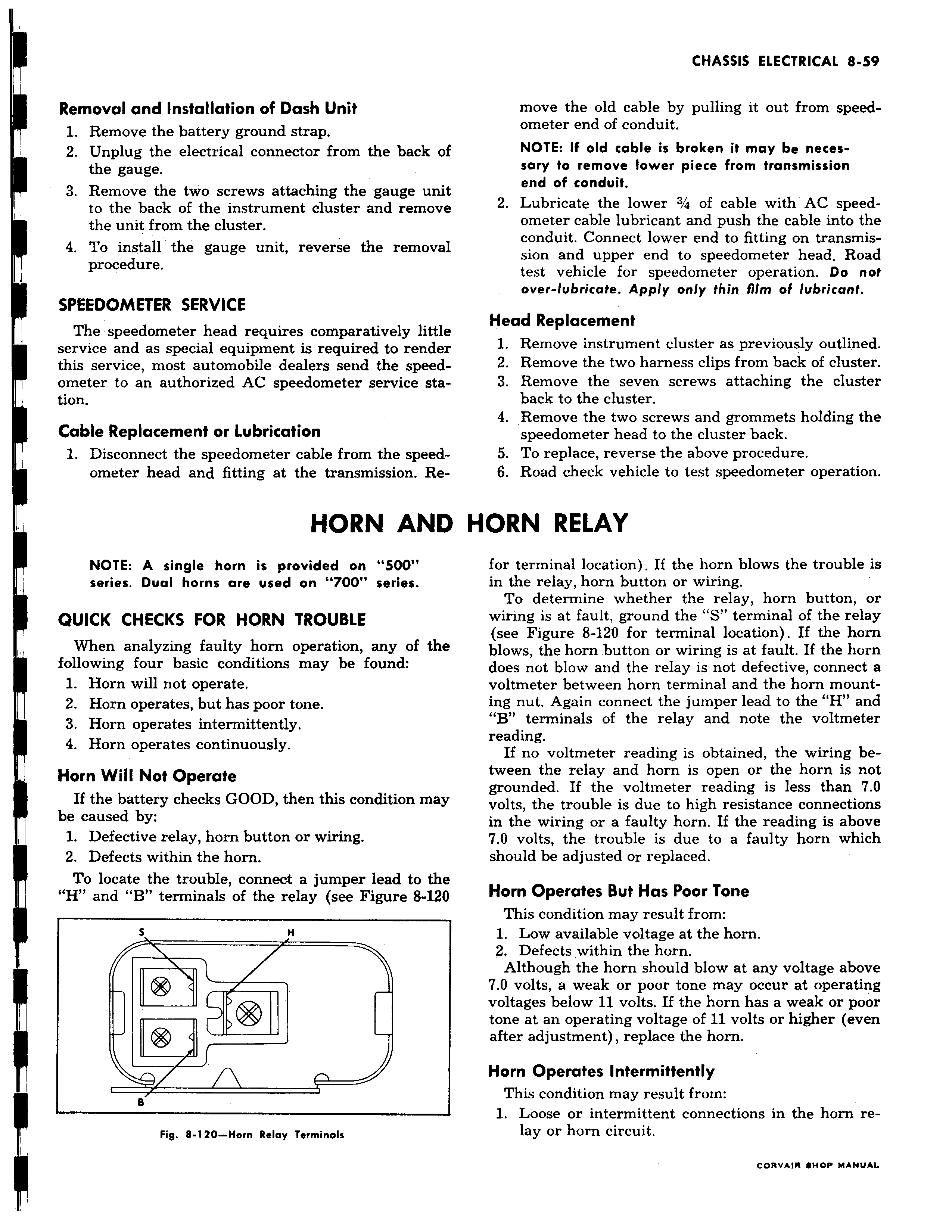
Removal and Installation of Dash Unit 1 Remove the battery ground strap 2 Unplug the electrical connector from the back of I the gauge 3 Remove the two screws attaching the gauge unit to the back of the instrument cluster and remove the unit from the cluster 4 To install the gauge unit reverse the removal procedure SPEEDOMETER SERVICE The speedometer head requires comparatively little service and as special equipment is required to render this service most automobile dealers send the speedometer to an authorized AC speedometer service station Cable Replacement or Lubrication 1 Disconnect the speedometer cable from the speedometer head and fitting at the transmission Re HORN AND NOTE A single horn is provided on 500 series Dual horns are used on 700 series QUICK CHECKS FOR HORN TROUBLE When analyzing faulty horn operation any of the following four basic conditions may be found 1 Horn will not operate 2 Horn operates but has poor tone 3 Horn operates intermittently 4 Horn operates continuously Horn Will Not Operate If the battery checks GOOD then this condition may be caused by 1 Defective relay horn button or wiring 2 Defects within the horn To locate the trouble connect a jumper lead to the H and B terminals of the relay see Figure 8 120 5 H i I B Fig 8 120 Horn Relay Terminals move the old cable by pulling it out from speedometer end of conduit NOTE If old cable is broken it may be necessary to remove lower piece from transmission end of conduit 2 Lubricate the lower 3 4 of cable with AC speedometer cable lubricant and push the cable into the conduit Connect lower end to fitting on transmis sion and upper end to speedometer head Road test vehicle for speedometer operation Do not over lubricate Apply only thin film of lubricant Head Replacement 1 Remove instrument cluster as previously outlined 2 Remove the two harness clips from back of cluster 3 Remove the seven screws attaching the cluster back to the cluster 4 Remove the two screws and grommets holding the speedometer head to the cluster back 5 To replace reverse the above procedure 6 Road check vehicle to test speedometer operation HORN RELAY for terminal location If the horn blows the trouble is in the relay horn button or wiring To determine whether the relay horn button or wiring is at fault ground the S terminal of the relay see Figure 8 120 for terminal location If the horn blows the horn button or wiring is at fault If the horn does not blow and the relay is not defective connect a voltmeter between horn terminal and the horn mounting nut Again connect the jumper lead to the H and B terminals of the relay and note the voltmeter reading If no voltmeter reading is obtained the wiring between the relay and horn is open or the horn is not grounded If the voltmeter reading is less than 7 0 volts the trouble is due to high resistance connections in the wiring or a faulty horn If the reading is above 7 0 volts the trouble is due to a faulty horn which should be adjusted or replaced Horn Operates But Has Poor Tone This condition may result from 1 Low available voltage at the horn 2 Defects within the horn Although the horn should blow at any voltage above 7 0 volts a weak or poor tone may occur at operating voltages below 11 volts If the horn has a weak or poor tone at an operating voltage of 11 volts or higher even after adjustment replace the horn Horn Operates Intermittently This condition may result from 7 Loose or intermittent connections in the horn relay or horn circuit