Jeep Parts Wiki | Ford Parts Wiki
Home | Search | Browse | Marketplace | Messages | FAQ | Guest
Prev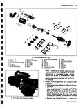
 Next
Next
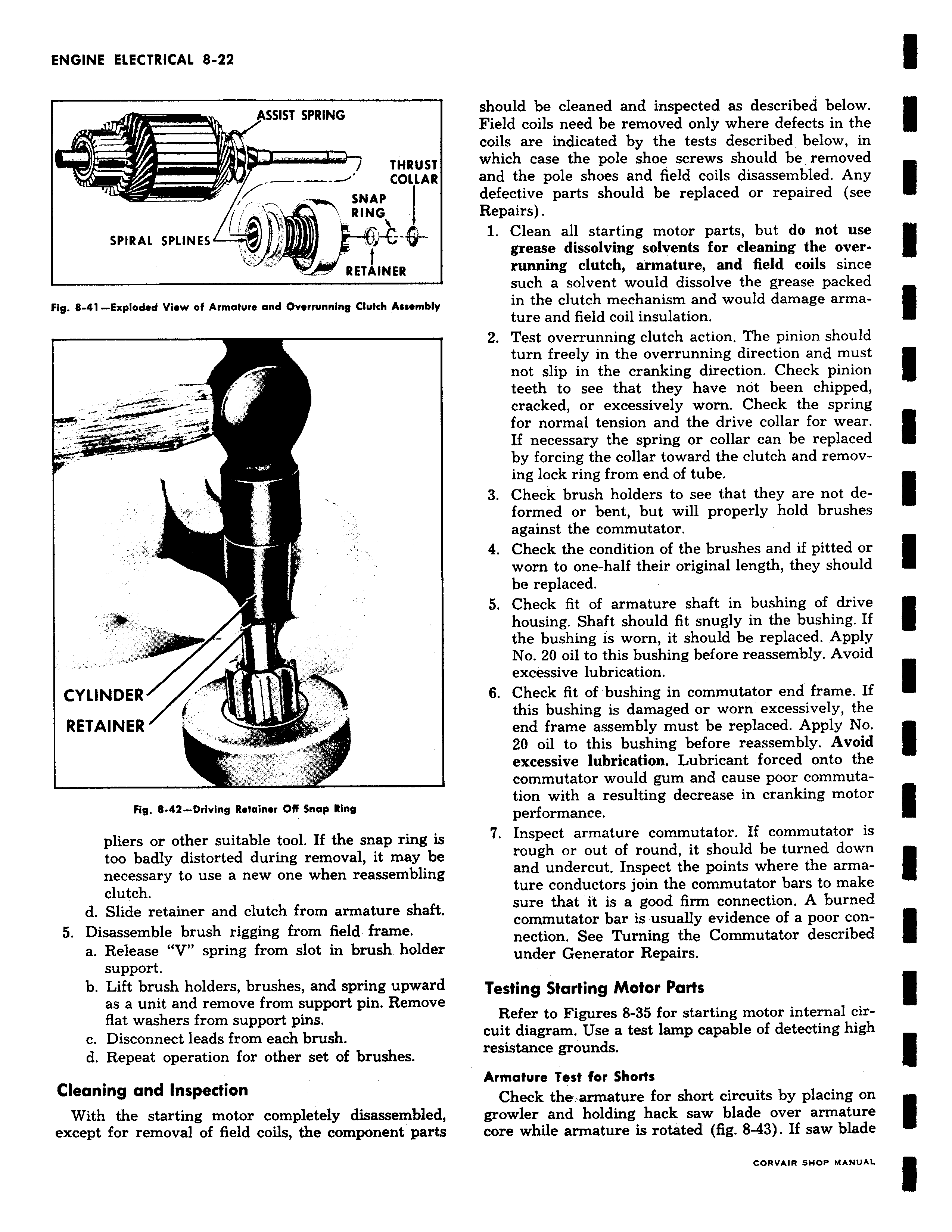
ASSIST SPRING THRUST COLLAR SNAP RINGy SPIRAL SPLINES RETAINER Fig 8 41 Exploded View of Armature and Overrunning Clutch Assembly CYLINDER RETAINER Fig 8 42 Driving Retainer OR Snap Ring pliers or other suitable tool If the snap ring is too badly distorted during removal it may be necessary to use a new one when reassembling clutch d Slide retainer and clutch from armature shaft 5 Disassemble brush rigging from field frame a Release V spring from slot in brush holder support b Lift brush holders brushes and spring upward as a unit and remove from support pin Remove flat washers from support pins c Disconnect leads from each brush d Repeat operation for other set of brushes Cleaning and Inspection With the starting motor completely disassembled except for removal of field coils the component parts should be cleaned and inspected as described below Field coils need be removed only where defects in the coils are indicated by the tests described below in which case the pole shoe screws should be removed and the pole shoes and field coils disassembled Any defective parts should be replaced or repaired see Repairs 1 Clean all starting motor parts but do not use grease dissolving solvents for cleaning the overrunning clutch armature and field coils since such a solvent would dissolve the grease packed in the clutch mechanism and would damage armature and field coil insulation 2 Test overrunning clutch action The pinion should turn freely in the overrunning direction and must not slip in the cranking direction Check pinion teeth to see that they have not been chipped cracked or excessively worn Check the spring for normal tension and the drive collar for wear If necessary the spring or collar can be replaced by forcing the collar toward the clutch and removing lock ring from end of tube 3 Check brush holders to see that they are not deformed or bent but will properly hold brushes against the commutator 4 Check the condition of the brushes and if pitted or worn to one half their original length they should be replaced 5 Check fit of armature shaft in bushing of drive housing Shaft should fit snugly in the bushing If the bushing is worn it should be replaced Apply No 20 oil to this bushing before reassembly Avoid excessive lubrication 6 Check fit of bushing in commutator end frame If this bushing is damaged or worn excessively the end frame assembly must be replaced Apply No 20 oil to this bushing before reassembly Avoid excessive lubrication Lubricant forced onto the commutator would gum and cause poor commutation with a resulting decrease in cranking motor performance 7 Inspect armature commutator If commutator is rough or out of round it should be turned down and undercut Inspect the points where the arma ture conductors join the commutator bars to make sure that it is a good firm connection A burned commutator bar is usually evidence of a poor connection See Turning the Commutator described under Generator Repairs Testing Starting Motor Parts Refer to Figures 8 35 for starting motor internal circuit diagram Use a test lamp capable of detecting high resistance grounds Armature Test for Shorts Check the armature for short circuits by placing on growler and holding hack saw blade over armature core while armature is rotated fig 8 43 If saw blade