Jeep Parts Wiki | Ford Parts Wiki
Home | Search | Browse | Marketplace | Messages | FAQ | Guest
Prev
 Next
Next
24128
24128
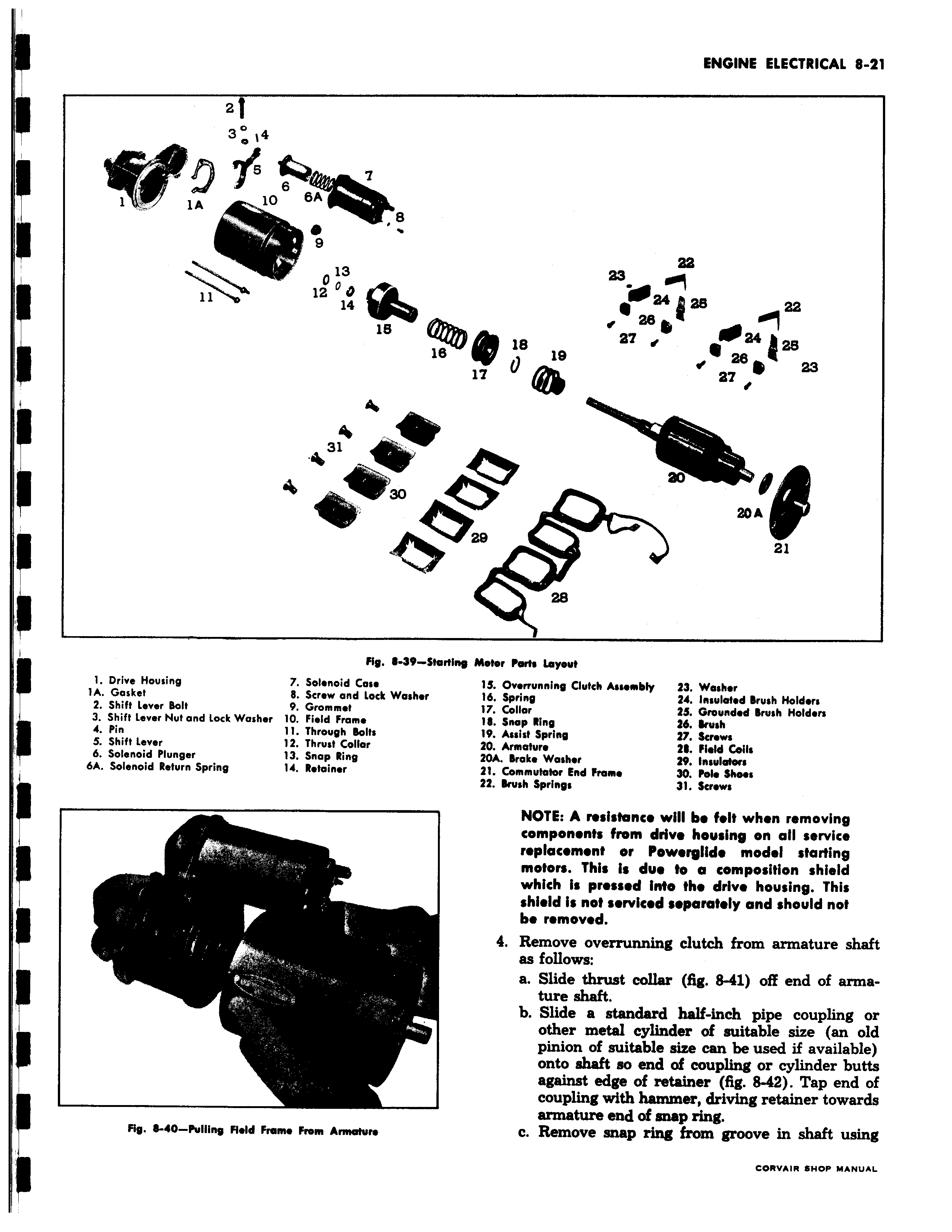
f i i 3 14 0 e 13 000 12 14 tW 31 s t r 22 I 0024128 22 fa8 41 18 27 4024 28 19 0 26 23 lz az 0 ao 20A 129 21 28 ng Motor Parts Layout 15 Overrunning Clutch Assembly 23 Washer 16 Spring 24 Insulated Brush Holders 17 Collor 23 Grounded Brush Holders 1 Snap Ring 26 Brush 19 Assist Spring 27 Screws 20 Armature 21 Field Coils 20A Broke Washer 29 Insulators 21 Commutator End frame 30 Palo Shoos 22 Brush Springs 31 Screws NOTE A resistance will be felt when removing component from drive housing on all service replacement or Powerglide model starting motors This is due to a composition shield which is pressed Into the drive housing This shield i not serviced separately and should not be removed 4 Remove overrunning clutch from armature shaft as follows a Slide thrust collar fig 8 41 off end of armature shaft b Slide a standard half inch pipe coupling or other metal cylinder of suitable size an old pinion of suitable size can be used if available onto shaft so end of coupling or cylinder butts against edge of retainer fig 8 42 Tap end of coupling with hammer driving retainer towards armature end of snap ring c Remove snap ring from groove in shaft using