Jeep Parts Wiki | Ford Parts Wiki
Home | Search | Browse | Marketplace | Messages | FAQ | Guest
Prev
 Next
Next
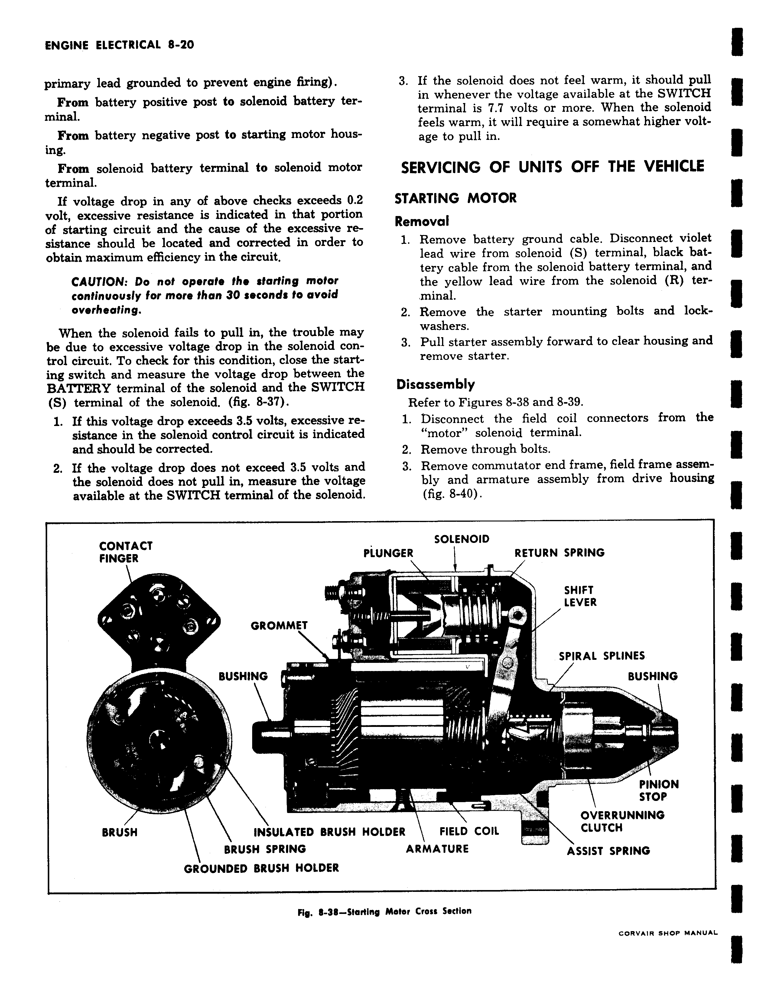
primary lead grounded to prevent engine firing From battery positive post to solenoid battery terminal From battery negative post to starting motor housing From solenoid battery terminal to solenoid motor terminal If voltage drop in any of above checks exceeds 0 2 volt excessive resistance is indicated in that portion of starting circuit and the cause of the excessive resistance should be located and corrected in order to obtain maximum efficiency in the circuit CAUTION Do not operate the starting motor continuously for more than 30 seconds to avoid overheating When the solenoid fails to pull in the trouble may be due to excessive voltage drop in the solenoid control circuit To check for this condition close the starting switch and measure the voltage drop between the BATTERY terminal of the solenoid and the SWITCH S terminal of the solenoid fig 8 37 1 If this voltage drop exceeds 3 5 volts excessive resistance in the solenoid control circuit is indicated and should be corrected 2 If the voltage drop does not exceed 3 5 volts and the solenoid does not pull in measure the voltage available at the SWITCH terminal of the solenoid CONTACT FINGER GROMMET BUSHING m BRUSH INSULATED BRUSH F BRUSH SPRING GROUNDED BRUSH HOLDER Fig 111 3111 Start 3 If the solenoid does not feel warm it should pull in whenever the voltage available at the SWITCH terminal is 7 7 volts or more When the solenoid feels warm it will require a somewhat higher voltage to pull in SERVICING OF UNITS OFF THE VEHICLE STARTING MOTOR Removal 1 Remove battery ground cable Disconnect violet lead wire from solenoid S terminal black battery cable from the solenoid battery terminal and the yellow lead wire from the solenoid R terminal 2 Remove the starter mounting bolts and lockwashers 3 Pull starter assembly forward to clear housing and remove starter Disassembly Refer to Figures 8 38 and 8 39 1 Disconnect the field coil connectors from the motor solenoid terminal 2 Remove through bolts 3 Remove commutator end frame field frame assembly and armature assembly from drive housing fig 8 40 SOLENOID LUNGER RETURN SPRING L SHIFT LEVER SPIRAL SPLINES BUSHING PINION STOP OVERRUNNING IOLDER FIELD COIL CLUTCH ARMATURE ASSIST SPRING ny Motor Cross Section CORVAIR SHOP MANUAL