Jeep Parts Wiki | Ford Parts Wiki
Home | Search | Browse | Marketplace | Messages | FAQ | Guest
|
Camaro Assembly Manual April 1968 |
|
Prev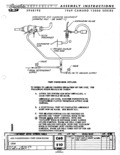
 Next
Next
3940195
3940195
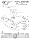
A s s E M B L Y 1 N s r R u c rr 0 N s 3940195 1969 CAMARO 12000 SERIES Evacuatlng and Charging the System 1 Remove cap from Expansion Valve inlet and P 0 A 9 l Valve 3 Attach Process Coupler Yoke Assembly to process valves uncapped in Step l 3 Attach quick connect fitting from vacuum system to Process Coupler and open valves slowly to evacuate Air Conditioning System 4 Air conditioning system mustbe evacuated to a minimum of 25 mm Hg absolute system pressure 1 After a 15 second hold time 2 me system pressure must not exceed 28 mm Hg absolute pressure 1 System Pressure the level of evacuation of the vehic1e s A C system once the vacuum source has been removed V 2 Hold Time elapsed time which occurs between vacuum disconnect and charge connect For those plants which have a longer than 15 second hold time the system pressure may be allowed to rise to the values shown below ln Table 1 Elapsed Time Between TABLE 1 Acceptable Evacuation l evel mm Hg Evacuation and Charge per Evacuation and Charge Spec 15 30 seconds 28 mm Hg 31 60 seconds 30 mm l lg 61 90 seconds 35 mm Hg 91 seconds andover 40 mm Hg 5 Disconnect quick connect fitting from vacuum system to Process Coupler and attach quick connect fitting from Refrigerant Charging Board to Process Coupler 6 Charge Air Conditioning system with specified amount of Refrlgerant A 7 Close valves on Process Coupler disconnect quick connect fitting from Charging Board to Process Coupler disconnect Process Coupler from Expansion Valve and P 0 A S l Valve and replace caps 81 Leak Test Systemr 9 Conduct FunctlonalTest 4 System Leak Test Limits 1 Except as noted in Z below all lines connectors land system components shall be free of leakage with a detector sensitivity calibration of 1 lb in 40 years 2 The compressor seal sight glass and Expansion Valve shall show no leakage with a detector sensitivity calibration of l lb in 5 years Functional Test A standard test of the function of the system is to be conducted in the following manner l Doors or windows open I I 2 Outlets knob at full left position Temp knob at COLD Full outside air position DEFR knob at OFF position V I 3 Temperature indicators at condenser inlet and center outlet l 4 9 4 Start engine and run at 2000 R P M I 5 After one minute the minimum drop in temperature of the air from the center outlet should be as follows couosusan INLET TEMP csmsn 0u rr m TEMP DR01 MLN FXGIIEQIKFEIK I cnevs0iET uoicq o v saoN GMCD UPC em rm rcvwoe co wm cx l f so nc 0 ice Ig V V AIR CONDlTIONTNG GEb ERAL SPECS z kg i g ks i Bf g PROCEDURES Q sx 4s4rrzsr ve l2iZj EE 8 12000 owoiz E1 REF E 0 L L 1 1 T5 Z 3 PF L L L I H DZi ALL